How to Create a Vector Portrait With Curly Hair in Adobe Illustrator

Final product image
What You’ll Be Creating

This tutorial was originally published in November 2012 as a Tuts+ Premium tutorial. It is now available free to view. Although this tutorial does not use the latest version of Adobe Illustrator, its techniques and process are still relevant. 

I’ve created several vector portrait tutorials in the past, but one request is made several times and that is how to create curly hair. In today’s tutorial, I’m going to show you one of the easiest ways of creating detailed curly hair. So let’s jump in and begin creating!

To create gorgeous portraits of your own, consider one of our amazing Adobe Illustrator Hair Brushes from GraphicRiver. Or enlist the help of a design professional to create your very own portraits from Envato Studio.

1. How to Prepare the Document

Step 1

I start by creating a New document and then File > Place my stock image onto the canvas. As I want the hair to be one of the biggest features of this composition, I want to make sure that it has enough space to garnish the attention of the viewer. 

I then set up my layers as shown in the Layers panel below. In the layer “BG” I have placed a white fill Rectangle (M) over the stock image set to 50% Opacity. This is to make the edges of my shapes more prominent against the stock image when I’m tracing shapes.

Prepare the layers

Step 2

I often use the default “Skintones” palette from Adobe Illustrator. You can access this by clicking on the drill-down menu in the Swatches panel > Open Swatch Library > Skintones. For Caucasian skin, I select the top four palettes so I can mix them to create multi-tone shading. Skin isn’t all one color—there are different shades depending on the area of the face/skin, which I’ll go into later on. By clicking on the folder to the left of the palette, you can automatically add them to your Swatches panel.

Adding palettes to the Swatches panel

I’ve then selected a mid tone and used the Pen Tool (P) to trace my overall skin base shape.

Trace with the pen tool

2. How to Render the Skin

Step 1

For the initial skin shading shapes, I’ve used the same skin tone as the base and traced areas of highlight on the face with the Pen Tool (P). I’ve then created a Compound Path (Control-8) with the first set of shapes and used Pathfinder > Minus Front from a duplicate of the skin base shape.

Skin shading

I use the same process several times. Once done, I set the shapes to Blending Mode Multiply, Opacity 10%, and then Group them (Control-G).

Skin shading

Step 2

Using a slightly darker skin tone, I trace areas of shadow with the Pen Tool (P). Again after one set is created, I’ll add it to its own Compound Path (Control-8). Each Compound Path is then set to Blending Mode Multiply, Opacity 10% and then Grouped together (Control-G).

Add darker shadows

Step 3

As you may have noticed, the shapes go beyond the base shape. I’ve duplicated the base shape and Grouped the two groups of skin shading shapes (Control-G) and then created a Clipping Mask (Control-7). All future skin shading shapes will be added to this Clipping Mask to keep a clean edge.

Create a Clipping Mask

Step 4

Using an even darker shade, I add darker shadows with the Pen Tool (P) using the same process. Typically the darker the area, the smaller the shapes created. These shapes are set to Blending Mode Multiply, Opacity 10%.

Add further shading

Step 5

Now to add the highlights. I create a transparent radial gradient using the lightest skin tone. I then use it to fill shapes highlighting areas of the skin. These shapes aren’t added to a Compound Path.

Add highlights

Instead each set of shapes is Grouped together (Control-G). Each set is set to Blending Mode Screen, Opacity 15%.

Add further highlights

Step 6

There are areas which are in deeper shadow than anywhere else. Typically it’s areas where the skin folds (eyelids, lips, nose crease), but also near the hairline, along the nose to help it stand out, and around the nostrils. These shapes are much darker and are set to Blending Mode Multiply, Opacity 15%.

Add darker shadows

Step 7

From the more pink hue skin tones, I’m going to add a light pink transparent radial gradient to the skin, first to just below the cheekbone within an Ellipse (L).

Add pink tones to the cheek

The next is on the shoulder. These shapes are set to Blending Mode Multiply, Opacity 60%. I’ve added the cheek coloring above the other skin shading, whereas the shoulder is below the skin shading.

add pink tones to the shoulder

Step 8

To modify the overall base of the skin shading, I’m going to add gradients below the rendered skin shading shapes. Duplicate the original base shape and first add transparent radial gradients with the highlight gradient. Using the Gradient Tool (G), move the sources of the gradients over the face and over the shoulder/arm. These are set to Blending Mode Screen, Opacity 30%.

Modify the base underneath the shading

I’ve then added a transparent linear gradient under the skin shading set to Blending Mode Color Burn, Opacity 100%.

Add shadows underneath the shading

Step 9

Using the skin highlighting radial gradient, I’ve then added more intense highlights to the eyeball and skin. These are set to Blending Mode Screen, Opacity 60%.

Add further highlights

Step 10

Skin isn’t all one color—there are a variety of tones throughout. Typically you’ll find a hint of grey towards the corner of the eyes. Use a transparent radial gradient set to Blending Mode Color to add a grey tint. Reduce the Opacity accordingly, although keep in mind that the more prominent the grey, the more aged a person will appear.

Add grey to the corner of the eyes

The tip of the nose typically is more rosy. So use a red radial gradient set to Blending Mode Color Burn, Opacity 20% to add a hint to the nose.
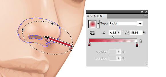
Add red to the nose

To make the cheekbones stand out more, add shading underneath them. I’ve added more color to the cheekbone with a purple transparent radial gradient. This is set to Blending Mode Color Burn, Opacity 10%.

Add more redpurple tones to the cheek

Step 11

To show the creases in the neck, I’ve added further highlights using the highlighting skin gradient. These are set to Blending Mode Screen, Opacity 30%.

Add further highlights to the neck

3. How to Render the Lips

Step 1

When I begin skin shading, I always treat the lips as if they have no color and shade them with the skin. This is because I don’t want the lips to look as if they are floating independently on top of the skin. 

I then use gradients to add color to the lips. I’ve used a pink transparent radial gradient on the three shapes I’ve created for the lips: one for the overall lips shape and one each for the top and bottom lips. They overlap in the center to help darken this area which is in shadow. These shapes are then set to Blending Mode Color Burn, Opacity 40%.

Add reds to the lips

Step 2

I use a brown transparent radial gradient to add shadow and creases to the lips. These shapes are set to Blending Mode Color Burn, Opacity 50%.

Add shadow to the lips

Due to the contrast created with these shapes, I’ve added further shading to the face with the same gradient. These shapes are set to Blending Mode Color Burn, Opacity 100%.

Balance the contrast

Step 3

With the Pencil Tool (N) and a light pink transparent radial gradient, add highlights to the lips. The Pencil Tool (N) will allow you to add many shapes much quicker than using the Pen Tool (P). These shapes are then set to Blending Mode Overlay, Opacity 30%.

Add highlights to the lips

Then using the highlighting skin gradient, add further more intense shapes. These are set to Blending Mode Color Dodge, Opacity 40%.

Add further highlights

Step 4

I want the lips to appear more pink than red/orange, so I duplicate the shape covering the whole of the lips area and add a dark blue transparent radial gradient. Set it to Blending Mode Soft Light, Opacity 100%. This helps “neutralise” the red/orange tone.
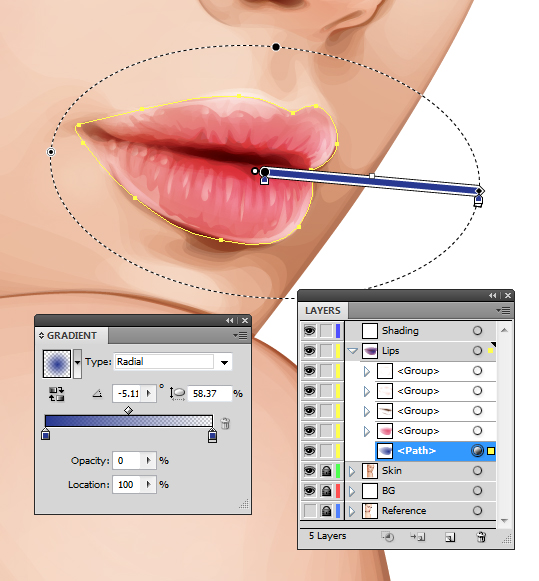
Use blue to make the lips more pink

4. How to Render the Eyes

Step 1

Using a similar theory, I’m going to “neutralize” the red/orange tones on the eyeballs slightly by using a light blue radial gradient. This will be set to Blending Mode Color and Opacity 30%.

Neutralise the eyes

Then I’m going to add highlights to the eyeball using the highlighting skin gradient set to Blending Mode Screen, Opacity 40%.

Add highlights to the eyes

Step 2

I’m going to add a pink tint to the water line with a rose transparent radial gradient set to Blending Mode Color, Opacity 100%.

Add pink to the waterline

Then add a bolder and darker gradient in the corner of the eyes set to Blending Mode Multiply, Opacity 30%.
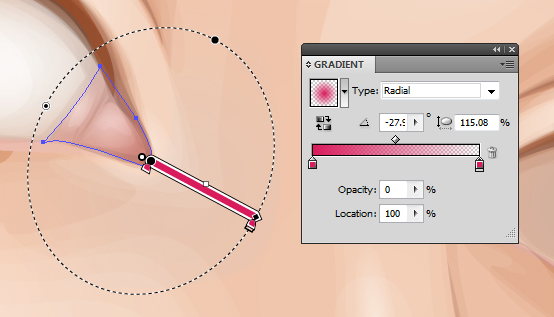
Add pink to the corner of the eyes

Step 3

With a golden brown fill color, use the Pencil Tool (N) to add shading around the waterline and corner of the eye. These shapes are set to Blending Mode Multiply, Opacity 10%.

Add details to the eyes

Then with a light pink, add highlights with the Pencil Tool (N) set to Blending Mode Screen, Opacity 40%.

Add details to the eyes

Step 4

I’m going to use Clipping Masks (Control-7) for the iris. First duplicate the largest shape for the eyeball. Then draw an even circle with the Ellipse Tool (L).

Create the eye

Create a Clipping Mask: first a duplicate of the iris and then a Clipping Mask containing this iris mask, with the eyeball duplicated shape. This will give you a Clipping Mask within a Clipping Mask. You will see the benefit of this soon.

Create a clipping mask

Step 5

I’ll be adding the detailing to the eyes via the Appearance panel. I’ve used a mid brown for the iris. The first fill is set to 60% Opacity, and the second from bottom fill is Offset Path by -1 pt and 100% Opacity. This gives the iris a soft edge. 

Then the pupil is made from two dark brown fills. One is Offset Path by -12 pt with a Blending Mode of Multiply, Opacity 40%. The next is Offset Path by -13 pt and with a Blending Mode of Multiply, Opacity 80%. Again this is to create a soft edge.

Create a soft edge to the eye

Step 6

Gradients are then added to the iris. These are Offset Path by -1 pt. An inverted dark brown radial gradient is applied to give a vignette effect around the iris.

Use gradients for the eyes

This is then duplicated and with the Gradient Tool (G) is enlarged and brought down towards the bottom of the iris. This gives a slight shadow at the top of the iris.

Add further gradients

Then a green to orange radial gradient is applied to the bottom of the iris. This is to give a golden brown tone to the eyes.

Adding further gradients

Step 7

Duplicate Item and give an Offset Path -1 pt and a dark brown transparent radial gradient fill. Then go to Effect > Transform & Distort > Zig-Zag and use the settings below. If the two Clipping Masks were not applied, the zig-zag effect would overlap onto the eyelid and onto the eyeball. Once done, go into the Graphic Styles panel and Add New Graphic Style and apply it to the other eye so you’ve got the same effects on both.

Use the Zig-Zag effect

Step 8

Using the Pen Tool (P) and a dark brown fill, draw shapes around the eye and eyelid crease. This is to help build upon a base for the eyelashes and to define the eyelids. These shapes are set to Blending Mode Multiply, Opacity 30%.

Add shading around the eyes

Further, more subtle shapes are added with a black fill, set to Blending Mode Multiply, Opacity 10%. These help to add shadow onto the eyeball.

Push the contrast

Step 9

Using the skin highlighting gradient, add a light reflection along the waterline and over the pupil. These are set to Blending Mode Screen, Opacity 70% to 100%.

Add highlights

Step 10

Eyelashes are added using the Width Profile 1 brush I’ve created in a previous tutorial. Both lashes use a dark brown stroke color, but the top are set to Blending Mode Multiply, Opacity 70%, and the bottom are set to Blending Mode Multiply, Opacity 40%.

Create the eyelashes

5. How to Render the Hair

Step 1

Before I begin adding the hair, I decide to sketch out ideas. I use the Blob Brush Tool (Shift-B) to sketch with. I Create New Layer above and below the core elements of the portrait to sketch hair on top and underneath the portrait. I’ve decided in this case I’m going to fill all the negative space with hair.

Sketching out the hair

Step 2

For curly hair, you need to treat each curl as its own entity. Each curl should cover any hair which is underneath it to create a mane of healthy, thick curls. One of the easiest ways of going about this is to create an Art Brush of a curl. Of course we’re not drawing an actual curl, but imagine pulling a curl straight.

Using the Rounded Rectangle Tool, draw out a shape and use the Direct Selection Tool (A) to select the end points of the shape. Then use the Free Transform Tool (E) to reduce the size at the end of the shape to create a tapered effect. I want to give the portrait a mass of green hair.

Create the base of a brush

Step 3

As you can’t include a gradient or a Clipping Mask with an Art Brush, I’m going to create a gradient effect using a Blend. Duplicate the tapered shape twice. Use the Free Transform Tool (E) to reduce the size of the shape on top. For the larger one, set it to 0% Opacity. Then with both shapes selected create a Blend (Control-Alt-B) with Specified Distance Spacing of 4 pt. Set the Blend to Blending Mode Multiply.

Use a blend instead of a gradient

Step 4

Using the Width Profile 3 brush, add strokes using the Line Segment Tool () at the tip of the tapered end with a 2 pt Stroke Weight. These strokes should be the same green as the original tapered shape and placed below the Blend.

Add additional strokes

Step 5

With the Width Profile 1 brush, add 2 pt Strokes with the Line Segment Tool () on top of the shape with Blending Mode Screen, Opacity 30% to add highlights. Then using the same settings, add darker strokes with a Blending Mode of Multiply, Opacity 30%. Group all the elements once done (Control-G).

Add additional strokes

While the group is selected, in the Brush panel create a New Brush > Art Brush and click on OK.

Create a New Art Brush

Step 6

Using the Pen Tool (P) for a smoother curve, add curls around the face underneath the face elements. Group them together once you’ve applied the initial curls (Control-G).

Begin using the Brush

Add the curls in groups so you can place them underneath the previous ones. The curls in front should be above all the others, and the curls at the back should be at the bottom of the layer.

Build up the layers of curls

Step 7

While layering the curls, for any gaps present I use a dark green shape to block the gaps.

Fill in the gaps

Then when I’ve finished the layering of curls, I add a dark green Rectangle (M) behind all the curls.

Create a background

Step 8

Using the Width Profile 1 brush and the Paintbrush Tool (B), I add strokes with a medium green along the sides of the curls and at the tip. As each curl is identical, I want to make them look more individual. So adding additional strokes helps me achieve this. These strokes are set to Opacity 80%.

Add strokes to make the curls more unique

I repeat this same method for the curls at the back and add them in stages.

Add further strokes

Step 9

With a lime green, I add 4 pt Stroke Weight, Width Profile 1 strokes to the curls. These are set to Blending Mode Color Dodge, Opacity 40%. These strokes add a highlight to the curls and give them further definition.

Add highlights

I then add 2 pt Stroke Weight strands to add more detail to the highlights. These are set to Blending Mode Screen, Opacity 40%.

Add further highlights

Step 10

Using the Pencil Tool (N), I add lime green transparent radial gradients over the top of the highlighted areas of the curls. This adds a smoother highlight to them. These are set to Blending Mode Color Dodge, Opacity 25%.

Use gradients to create highlights

6. How to Create the Eyebrows

The finishing touches are to add eyebrows. I’ve used the Width Profile 1 brush to add 1 pt strokes to the brow bone. The initial strokes are set to Blending Mode Normal, Opacity 80%.

Add the initial strokes

Finishing off with some strokes set to Blending Mode Multiply, Opacity 50%.

Add darker further strokes

Awesome Work, You’re Now Done!

If you’ve followed my tutorials in the past, you’ll know I finish off with a couple of moles to the face and skin. These are created using two-layered brown transparent radial gradients set to Blending Mode Multiply. I hope you’ve enjoyed this tutorial and learnt one of the methods possible for creating curly hair.
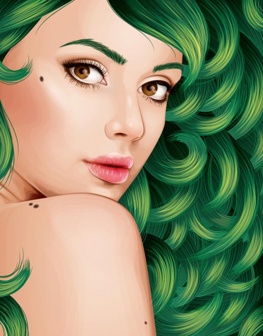
Vector Curly Hair Tutorial by Sharon Milne

Adobe Illustrator Hair Brushes From GraphicRiver

To help save time with your next fabulous portrait, consider using one of the amazing Adobe Illustrator Hair Brushes from GraphicRiver to speed things up. Check out one of these helpful brush packs below!

Easy Hair Brushes for Adobe Illustrator

Create quick hairstyles like a pro with this amazing brush pack! It’s designed with 17 easy hair brushes, so you can simply drag and drop the brushes into the preset folder to begin creating realistic hair of your own in no time! Ideal for use with the Pen Tool, you can also use these brushes with a mouse or graphics tablet!

Easy Hair Brushes for Adobe Illustrator

How to Create a Set of Divider Elements in Adobe Illustrator

Final product image
What You’ll Be Creating

In today’s
tutorial we’re going to try something new both to me and probably some of you,
and learn how to create a set of stylized divider elements, using the Pen Tool in combination with some basic
shapes which we will adjust here and there.

So assuming you already have Illustrator running in the background,
bring it up and let’s get started!

Oh, and don’t forget you can always find more vector divider elements over on GraphicRiver.

1. How to Set Up a
New Project File

As with any other
project, we’ll have to create a New
Document
(File > New or Control-N) and tailor that according to our needs:

  • Number
    of Artboards:
    1
  • Width:
    800
    px
  • Height:
    600
    px
  • Units:
    Pixels

And from the Advanced tab:

  • Color
    Mode:
    RGB
  • Raster
    Effects:
    Screen (72ppi)
  • Preview Mode: Default
setting up a new document

2. How to Set Up a
Custom Grid

Now, I know we’re not working on icons
today, but since we’re going to be creating the dividers using a pixel-perfect
workflow, we’ll want to set up a nice little grid so that we can have full
control over our shapes.

Step 1

Go to the Edit > Preferences > Guides & Grid submenu, and adjust
the following settings:

  • Gridline
    every:
    1 px
  • Subdivisions: 1
setting up a custom grid

Quick
tip:
you can learn more about grids by reading this
in-depth piece on how Illustrator’s Grid System works.

Step 2

Once we’ve set up our custom grid, all we
need to do in order to make sure our shapes look crisp is enable the Snap to Grid option found under the View menu, which will transform into Snap to Pixel each time you enter Pixel Preview mode.

Now, if you’re new to
the whole “pixel-perfect workflow”, I strongly recommend you go through my how
to create pixel-perfect artwork
tutorial, which will help you widen your
technical skills in no time.

3. How to Create the Middle Divider

We’re going to kick things off by creating
the middle divider, so that we can create and position the other two in
relation to it.

Step 1

Using the Rectangle Tool (L), create a 16 x 16 px square, which we will color
using #4adbc8 and then center align to the Artboard
using the Align panel’s Horizontal and Vertical Align Center options.

creating and positioning the main shape for the middle dividers center section

Step 2

Turn the square that
we’ve just created into a diamond, by selecting the Add Anchor Point Tool (+) and using it to add a new anchor to the
center of each of its sides, removing the corner ones (highlighted with red)
using the Delete Anchor Point Tool (-).

adjusting the main shape of the middle dividers center section

Step 3

Give the resulting shape
an outline using the Stroke method,
by creating a copy of it (Control-C > Control-F) which we will adjust by first changing its
color to #352f2f and flipping its Fill with
its Stroke (Shift-X). After that, make sure to set its Weight to 4 px and its Corner to Round Join, selecting and grouping both shapes together using the Control-G keyboard shortcut.

adding the outline to the main shape of the middle dividers center section

Step 4

Create the outer
diamond using a 40 x 28 px rectangle
(#352f2f) which we will adjust using the same process of adding the new
anchor points to the center of its sides, and then removing its corner ones.
Turn the resulting shape into an outline by flipping its Fill with its Stroke (Shift-X), making sure to set its Weight to 4 px and its Corner to Round Join, center aligning it to the
previously grouped shapes afterwards.

creating and positioning the main shape for the middle dividers second center diamond

Step 5

Add the top circular
piece using a 6 x 12 px ellipse (#4adbc8)
with a 4 px thick outline (#352f2f), which we will group (Control-G) and
then position above the smaller diamond, center aligning the two.

creating and positioning the main shapes for the middle dividers top decorative ellipse

Step 6

Create a copy (Control-C > Control-F) of the shapes
that we’ve just grouped, and position it on the opposite side of the smaller
diamond piece, selecting and grouping all the sections that we have so far
together using the Control-G keyboard
shortcut.

creating and positioning the main shapes for the middle dividers bottom decorative ellipse

Step 7

Start working on the
divider’s left arm by creating the elongated diamond using a 58 x 14 px rectangle (#4adbc8), which we
will adjust by first turning on Pixel
Preview
mode (Alt-Control-Y) and
then adding a set of anchor points to the center of its side sections. Add
another set to its top and bottom sides, only this time make sure to position
them at a distance of 18 px from its
left edge, removing all the corner ones once you’re done.

creating and positioning the main shape for the middle dividers left elongated diamond

Step 8

Give the resulting
shape a 4 px thick outline (#352f2f)
with a Round Join, grouping (Control-G) and then positioning the two
shapes on the left side of the divider’s center section, at a distance of 8 px from its smaller diamond.

adding the outline to the middle dividers elongated diamond

Step 9

Using the Pen Tool (P), connect the elongated diamond to the smaller center one by drawing
an 8 px wide 4 px thick Stroke line
(#352f2f).

connecting the middle dividers elongated diamond to the smaller center one

Step 10

Continue working on
the arm by creating a 10 x 10 px square
(#352f2f) which we will adjust by turning it into a diamond with a 4 px thick outline and a Round Join. Once you’re done, position
the resulting shape on the left side of the elongated diamond, Vertically Center Aligning the two
using the Align panel.

adding the outline diamond to the middle dividers left arm

Step 11

Add the little
circular piece using a 12 x 6 px ellipse
(#4adbc8) with a 4 px thick outline
(#352f2f), which we will group (Control-G)
and then position on the left side of the previously created shape.

adding the decorative ellipse to the middle dividers left arm

Step 12

Using the Pen Tool (P), draw a 64 px wide 4 px thick Stroke line
(#352f2f), which we will position on the left side of the circular piece that
we’ve just created.

creating and positioning the horizontal stroke line onto the middle dividers left arm

Step 13

Create a 12 x 8 px ellipse, which we will color
using #352f2f and then position on the left end of the stroke line, center
aligning it to the anchor itself.

adding the ellipse onto the left side of the middle dividers left arm

Step 14

Create a 12 x 12 px circle with a 4 px thick Stroke (#352f2f) and a Round
Join
, which we will position on the left side of the previously created ellipse.

creating and positioning the larger circle onto the middle dividers left arm

Step 15

Adjust the shape that
we’ve just created by pinching its left anchor point using the Anchor Point Tool (Shift-C), and then selecting and pushing it to the left by a
distance of 10 px using the Move Tool (right click > Transform > Move > Horizontal > -10 px).

adjusting the shape of the middle dividers larger circle

Step 16

Make a copy (Control-C > Control-F) of the arm’s
elliptical piece, and position it on the left side of the circle that we’ve
just finished adjusting.

adding the second decorative ellipse to the middle dividers left arm

Step 17

Using the Rectangle Tool (M), create an 18 x 8 px shape (#4adbc8) which we will
turn into a diamond, selecting and then pushing its top and bottom anchors to
the right side by a distance of 4 px
(right click > Transform > Move
> Horizontal > 4 px
). Give the resulting shape a 4 px thick outline (#352f2f) with a Round Join, grouping (Control-G) and then positioning the two shapes
on the left side of the smaller ellipse.

adding the pointed decorative piece to the middle dividers left arm

Step 18

Finish off the left
arm by creating a 4 x 4 px circle,
which we will color using #352f2f and then position on the left side of the
pointed diamond, at a distance of 4 px.
Once you’re done, select and group all of the arm’s composing sections together
using the Control-G keyboard
shortcut.

finishing off the middle dividers left arm

Step 19

Finish off the
current divider by creating a copy (Control-C
> Control-F
) of its left arm, which we will vertically reflect (right click > Transform > Reflect
> Vertical
) and then position on the opposite side of the center diamond.

finishing off the middle divider

4. How to Create the Top Divider

Assuming you’ve managed to finish off the
middle divider, move a few pixels towards the top, and let’s start working on
the top one.

Step 1

Create the flower’s
center element using a 6 x 6 px circle,
which we will color using #352f2f and then center align to the Artboard, positioning it at a distance
of 44 px from the middle divider.

creating and positioning the main shape for the top dividers center section

Step 2

Start working on the
flower’s petals by creating
a 12 x 12 px circle, which we will
color using #4adbc8 and then position on top of the previously created shape,
at a distance of 2 px from it.

creating and positioning the main shape for the top dividers top petal

Step 3

Adjust the shape that
we’ve just created, by pinching its top anchor point using the Anchor Point Tool (Shift-C), and then selecting and pushing it to the top by a
distance of 2 px using the Move Tool (right click > Transform > Move > Vertical > -2 px).

adjusting the shape of the top dividers top petal

Step 4

Finish off the petal
by giving the shape a 4 px thick
outline (#352f2f) with a Round Join
followed by a 6 x 6 px circle (#352f2f)
which we will center align to its bottom edge, positioning it at a distance of
just 1 px. Once you’re done, select
and group all three shapes together using the Control-G keyboard shortcut.

finishing off the top dividers first petal

Step 5

Create the bottom
petal using a copy (Control-C >
Control-F
) of the one that we’ve just finished working on, which we will
horizontally reflect (right click >
Transform > Reflect > Horizontal
) and then position on the opposite
side of the smaller circle.

creating and positioning the main shapes for the top dividers bottom petal

Step 6

Add the remaining petals
using a copy (Control-C > Control-F) of the two that we
already have, which we will then rotate at a 90º angle using the Rotate
tool (right click > Transform >
Rotate > 90
).

creating and positioning the main shapes for the top dividers remaining petals

Step 7

Finish off the divider’s
center section by creating four 10 x 10
px
circles with a 4 px thick Stroke (#352f2f), which we will use to
form a square by positioning them at a distance of 8 px from one another, both horizontally and vertically. Once
you’re done, send all four shapes to the back of the flower (right click > Arrange > Send to Back),
grouping them and the remaining shapes together using the Control-G keyboard shortcut.

adding the decorative circles to the top dividers flower

Step 8

Start working on the
divider’s left arm by creating two 6 x 6
px
circles (#352f2f) which we will vertically stack 12 px from one another, grouping (Control-G) and then positioning them at a distance of 2 px from the flower’s decorative
circles.

creating and positioning the two decorative circle onto the top dividers left arm

Step 9

Continue working on the
arm by creating a 12 x 6 px ellipse
(#4adbc8) with a 4 px thick outline
(#352f2f), which we will group (Control-G)
and then center align to the larger flower, positioning them at a distance of 6 px from it.

adding the first decorative ellipse to the top dividers left arm

Step 10

Create another 6 x 6 px circle (#352f2f) and position
it on the left side of the decorative ellipse, at a distance of just 4 px.

adding the third decorative circle to the top dividers left arm

Step 11

Using the Pen Tool (P), draw a 116 px wide 4 px thick Stroke line
(#352f2f) with a Round Cap, and then
center align it to the decorative circle that we’ve just created, positioning
it at a distance of 4 px from it.

creating and positioning the horizontal stroke line onto the top dividers left arm

Step 12

Add the little right-facing arrows by drawing them using a 4
px
thick Stroke (#352f2f) with a
Round Cap. Once you’re done, select
and group (Control-G) all three
shapes together, aligning them to the right side of the horizontal divider line
afterwards.

adding the three right facing arrows onto the top dividers left arm

Step 13

Create a fourth 6 x 6 px decorative circle (#352f2f)
and position it on the left side of the horizontal stroke line, at a distance
of just 4 px.

creating and positioning the fourth decorative circle onto the top dividers left arm

Step 14

Move a few pixels
towards the left and create a 12 x 8 px ellipse
(#4adbc8) with a 4 px thick outline
(#352f2f) which we will group (Control-G),
and then position on the left side of the previously created circle, at a
distance of 4 px.

adding the second decorative ellipse onto the top dividers left arm

Step 15

Next, create two 6 x 6 px circles with a 4 px thick Stroke (#352f2f) which we will vertically stack, group (Control-G) and then position on the
left side of the decorative ellipse.

adding the vertically stacked circles onto the top dividers left arm

Step 16

Create another set of
10 x 10 px circles with a 4 px thick Stroke (#352f2f) and a 2 x 2
px
circle (#352f2f) in the center of each one, which we will group (Control-G) and then center align to the
previous set.

adding the second set of vertically stacked circles onto the top dividers left arm

Step 17

Start working on the
left-facing petal by creating its main body using a 14 x 14 px circle (#4adbc8) (1) which we will adjust by pinching
its left anchor point using the Anchor
Point Tool
(Shift-C) and then
pushing it to the left by a distance of 2
px
(right click > Transform >
Move > Horizontal > -2 px
) (2). 

Give the resulting shape a 4 px thick outline (#352f2f) with a Round Join followed by a 6 x 6 px circle with a 4 px thick Stroke (#352f2f) (3), grouping (Control-G) and positioning all three shapes on the left side of
the previously created shapes (4). Once you’re done, select all of the left
arm’s composing sections and group (Control-G)
those together as well.

finishing off the top dividers left arm

Step 18

Finish off the divider by creating its
right arm using a copy (Control-C >
Control-F
) of the one that we’ve just finished working on, which we will
vertically reflect (right click >
Transform > Reflect > Vertical
) and then position on the opposite
side of the center flower.

Once you’re done,
don’t forget to select and group all of the divider’s composing sections using
the Control-G keyboard shortcut.

finishing off the top divider

5. How to Create the Bottom Divider

We are now down to our third and last
divider, so without wasting any more time, let’s wrap things up!

Step 1

Start working on the
center section by creating a 14 x 32 px rectangle,
which we will color using #4adbc8 and then center align to the middle divider,
positioning it at a distance of 28 px from
it.

creating and positioning the main shape for the bottom dividers center section

Step 2

Turn the rectangle
into a diamond by adding a new anchor point to the center of each of its edges
with the help of the Add Anchor Point
Tool (+)
, removing the corner ones afterwards using the Delete Anchor Point Tool (-). Give the
resulting shape a 4 px thick outline
(#352f2f) with a Round Join, and
then group the two together using the Control-G
keyboard shortcut.

adding the outline to the main shape of the bottom dividers center section

Step 3

Create a 36 x 24 px ellipse with a 4 px thick outline (#352f2f) and a Round Join, which we will adjust by
pinching its side anchor points using the Anchor
Point Tool
(Shift-C), center
aligning the resulting shape to the previously created diamond, making sure to
position it underneath it (right click
> Arrange > Send to Back
). Once you’re done, select and group both it
and the diamond together using the Control-G
keyboard shortcut.

finishing off the bottom dividers center section

Step 4

Start working on the
divider’s left arm by creating a 10 x
10 px
ellipse (#4adbc8) which we will adjust by pinching its side anchors
using the Anchor Point Tool (Shift-C). Give the resulting shape a 4 px outline (#352f2f) with a Round Join, followed by an 8 x 8 px circle with a 4 px thick Stroke (#352f2f) towards its right side, grouping (Control-G) and then positioning all
three shapes on the left side of the center section.

creating and positioning the main shapes for the bottom dividers left petal

Step 5

Add two 8 x 8 px circles with a 4 px thick Stroke (352f2f) which we will vertically stack at a distance of 6 px from one another, grouping (Control-G) and then positioning them between the center section and the petal that we’ve just created.

adding the two vertically stacked circles to the bottom dividers left arm

Step 6

Create a 6 x 6 px circle, which we will color
using #352f2f and then position on the left side of the divider’s petal, at a
distance of 5 px.

adding the first decorative circle to the bottom dividers left arm

Step 7

Add the decorative bean
by creating a 12 x 8 px ellipse (#4adbc8)
with a 4 px thick outline (#352f2f),
which we will group (Control-G) and
then position on the left side of the previously created shape, at a distance
of just 4 px.

creating and positioning the main shapes for the bottom dividers first decorative bean

Step 8

Add the second
decorative circle using a 6 x 6 px shape
(#352f2f), which we will position on the left side of the bean, at a distance
of 4 px.

adding the second decorative circle to the bottom dividers left arm

Step 9

Using the Pen Tool (P), draw a 102 px wide 4 px thick Stroke line
(#352f2f) with a Round Cap, and then
center align it to the decorative circle that we’ve just created, positioning
it at a distance of 4 px from it.

creating and positioning the horizontal stroke line onto the bottom dividers left arm

Step 10

Add the little right-facing arrows by drawing them using a 4
px
thick Stroke (#352f2f) with a
Round Cap. Once you’re done, select
and group (Control-G) all three
shapes together, positioning them on the left side of the horizontal divider
line.

adding the three little right facing arrows to the bottom dividers left arm

Step 11

Create a 16 x 10 px rectangle (#4adbc8), which we
will turn into an elongated diamond by adding a set of new anchor points to
its sides, removing all the corner ones. 

Then, adjust the new shape by
selecting its top and bottom anchors and pushing them to the right by a
distance of 2 px (right click > Transform > Move >
Horizontal > 2 px
). Give the resulting shape a 4 px thick outline (#352f2f) with a Round Join, grouping (Control-G)
and then positioning the two shapes on the left side of the arrows, at a
distance of 5 px.

finishing off the bottom dividers left arm

Step 12

Finish off the divider by selecting and
grouping (Control-G) all of its left
arm’s composing sections together, and then creating a copy of them which we
will vertically reflect (right click
Transform > Reflect > Vertical
) and then position on the opposite
side of its center section.

Once you’re done,
don’t forget to group (Control-G)
all of the divider’s composing sections as well, so that they won’t get
separated if you move them.

finishing off the bottom divider

It’s a Wrap!

There you have it: a sweet-looking divider set created using some basic shapes and tools. I
hope that you’ve managed to keep up with each and every step, and learned
something new and helpful along the way.

How to Create a Desktop Illustration in Adobe Illustrator

Final product image
What You’ll Be Creating

In this tutorial I will show you how to create an amazing night desktop using basic shapes and tools in Adobe Illustrator. It’s very easy and fun!

If you’re looking for inspiration to create your own vector scenes, why not pop over to GraphicRiver.

1. How to Create a New Document and Set Up a Grid

Press Control-N to make a New Document. Set the Units to Pixels, and enter 800 x 600 for the width and height of the document. Then in the Advanced options, select RGBScreen (72 ppi), and make sure to activate the Align New Objects to Pixel Grid box before clicking OK.

Activate the Grid (View > Show Grid) and Snap to Grid (View > Snap to Grid). You’ll need a grid every 10 px, so simply press Control-K to go to Preferences, and in Guides & Grid set Gridline every to 10 and Subdivisions to 4. Don’t worry—the grid will help you work in an easy way, and it can also be enabled or disabled by pressing the keyboard shortcut Control-“.

You can activate the Info panel (Window > Info) in order to have a preview of the size and position of your shapes. Remember to set the measuring unit to Pixels from Edit > Preferences > Units. This will greatly increase the speed of your work.

Set Up a Document with a canvas of 800 x 600 px

2. How to Create a Desk

Let’s start by creating what will hold all our equipment, the
desk. To do this, we will use very basic shapes like rectangles and a few
ellipses for the drawers.

Step 1

Start by creating the top of the desk with a 536 x 16 px rectangle
using the Rectangle Tool (M). Use #61627C as the fill color.

Add a 460 x 52 px rectangle for the drawers, and use #484E69 as the fill color.

Creating the top of the desk

Step 2

Now, add the desk’s legs using two 24 x 148 px
rectangles. Afterwards, apply a linear gradient and select #565C79 as the fill color. Choose 100% Opacity at the top and 0% Opacity at
the bottom, as shown in the picture.

You can use the Gradient Tool (G) to make it easier.

Creating the legs of the desk and applying a gradient

Step 3

Now draw the desk’s drawers using a 208 x 32 px
rectangle. Select #61627C as the fill color and change the radius of all corners to 6
px
from the Transform panel.

Add the drawer’s handle creating a 12 x 12 px
ellipse with the Ellipse Tool (L) and use #8C8398 as the fill color.

Group everything together, duplicate (Control-C > Control-F) the drawer, and place both of them as shown in the image below.

Adding twos drawers to the desk

3. How to Create a MacBook

Step 1

The first device on the desk will be a
MacBook. Create a 184 x 10 px rectangle and enter 4 px as the corner radius for all corners. Use #7CEECE as the fill color.

Create another 48 x 8 px rectangle and change
the corner radius to 4 px. Subtract this rectangle from the other one using the
Minus Front utility from the Pathfinder panel. This will be the base.

Creating the base of the macbook

Step 2

For the laptop screen, create a 164 x 116 px
rectangle. Set all corner radiuses to 6 px and use #7CD5C2 as the fill color. Add
another 52 x 4 px rectangle under the base, use #7CBDA7 as the fill color.

Place both rectangles under the base (Object > Arrange >
Send Backward
).

Adding a rectangle for the cover

Step 3

Add the screen by creating a 152 x 98 px rectangle, and use #7566A6 as the fill color. Add the FaceTime camera by creating a 2 x 2 px
ellipse, and select #7CBDA7 as the fill color. 

Adding another rectangle for the screen

Step 4

Add reflections to the screen using two
rectangles (#FFFFFF), one of 172 x 44 px and
another one of 8 x 172 px. Rotate them 45º with the Rotate Tool (R) and select 50% Opacity on the Appearance
panel.

Select the laptop screen and the two
rectangles and subtract the edges with the Shape Builder Tool (Shift-M). Group
everything together (Control-G) and position it all as shown in the image below.

Adding a highlights to the screen

4. How to Create a Mac

Step 1

Now let’s draw the Mac. Start by creating the
base with a 74 x 8 px rectangle. Set the corner radius to 4 px and select #7CEECE as the fill color.

Add another 50 x 44 px rectangle (#7CD5C2) and modify the upper
width with the Free Transform Tool (E) to create a trapezoid. Then, create a 10 x 20 px rectangle, set its
corner radius to 6 px, and subtract it from the previous rectangle using the
Minus Front utility from the Pathfinder panel.

Creating rectangles for the base of the Mac

Step 2

Let’s continue with the Mac’s monitor. Create
a 222 x 130 px rectangle (#7CEECE). Enter 12 px as the corner radius.

Add the screen using a 204 x 106 px rectangle (#7566A6) and the FaceTime camera
with a 4 x 4 px ellipse (#7CBDA7). 

Twos rectangles for the monitor and the screen

Step 3

Add reflections to the screen following the
same procedure as for the MacBook. Add two rectangles (#FFFFFF), set their Opacity to
50%, and rotate them 45º.

Remove the edges with the Shape Builder Tool
(Shift-M)
. Group together all the Mac’s pieces (Control-G) and position it as
shown in the image below.

By adding the highlights over the screen

5. How to Create a Lamp

Every desk needs a cute desk lamp to
illuminate the space, so let’s go for it.

Step 1

Let’s begin by creating the base using a 78 x 12
px
rectangle (#897FBA) and set the radius of the upper
corners to 12 px

By creating a base for the lamp

Step 2

Now, add the first arm of the lamp using a
12 x 90 px rectangle (#7566A6) and rotate it 330°
using the Transform panel. Add an 18 x 18
px
ellipse (#9DA0CC) at the end of the arm.

Remember to place the arm under the base
(Object > Arrange > Send Backward).

By creating arm and hinge at the lamp

Step 3

Add a second arm using a 12 x 140 px rectangle
and an inclination of 55°. Place it under (Right click > Arrange > Send
Backward
) the hinge as shown in the image below.

Another arm tilted

Step 4

Now let’s create the lamp’s upper base using a
16 x 20 px rectangle (#9DA0CC) and set the radius of the upper
corners to 8 px. Add another 70 x 44
px
rectangle (#897FBA) and modify the upper
width with the Free Transform Tool (E).

Finally, drag the upper vertices using Live
Corners
with the Direct Selection Tool (A).

By drawing lamp with rectangles

Step 5

Add the ring lamp with a 72 x 8 px rectangle (#9DA0CC) and set the corner radius to 4 px. Group everything together
(Control-G) and rotate it 340°

Group together the whole body of the lamp
(Control-G) and position it as shown in the image below.

Placing the lamp in the body

6. How to Create a Cup of Coffee

And for long work hours, it is always good to
have a cup of coffee on the side. 

Moving on!

Step 1

Create a 36 x 52 px rectangle (#897FBA) for
the cup, and modify the lower corners with the Free Transform Tool (E) using the Perspective Distort feature.

Add another 38 x 18 px rectangle for the band of
the cup (#BEB2FF) and stretch the lower corners.

Creating the base body of coffee

Step 2

Now add the cup lid using a 42 x 6 px rectangle (#EDEEF0) and a 32 x 4 px
rectangle (#D8D9DD). Group everything
together (Control-G) and position it as shown in the image below.

Adding the cup ring and the cover

7. How to Create a Clock

We’re about to finish!

Now let’s create a clock for our workspace.

Step 1

Create a 112 x 112 px ellipse (#4E5471) for
the base of the clock. Duplicate (Control-C > Control-F) the ellipse and change
its size to 94 x 94 px (#61627C) using the Transform panel.

Add a 4 x 14 px rectangle (#818196) and
round its corners. Then, using the Rotate Tool (R), fix the anchor point to the
center of the ellipse and make three copies (Control-D) of the rectangle, each
separated by 90°.

Creating the clock base with ellipses

Step 2

Now we need to create the clock’s hands, so start
by creating a 4 x 46 px rectangle (#9DA0CC) as the minute hand. Round all the corners of the rectangle.
Place it in the center of the dial and rotate it with the Rotate Tool (R), fixing the anchor point to the center.

Add an 8 x 46 px rectangle (#818196) as
the hour hand and round its corners. Rotate it with the Rotate Tool (R).

Finally, add a 14 x 14 px ellipse (#BAB5C1) in
the center of the clock. Group everything together (Control-G) and position it as shown in the image below.

Adding the hands of the clock

8. How to Create a Background

Step 1

Let’s begin by creating a few stars using a
4 x 14 px rectangle (#7CEECE) with rounded corners. Then duplicate it (Control-C > Control-F)
and rotate it 90º. Group everything together (Control-G) and duplicate it
six times, alternating between #7CEECE and #9DA0CC as the fill colors.

Play a little with the sizes and position it as
shown in the image below.

Creating the stars for the background with rectangles

Step 2

Now let’s create an 800 x 600 px rectangle (#333656), the same size as the canvas, and send it to the back (Right click > Arrange >
Send to Back
).

Then, as a final detail, draw a trapezoid with
the Pen Tool (P) in the lamp, and then apply a linear gradient using #00FFFF and #FFFFFF as the fill colors. Set the Opacity to 0% for the #FFFFFF color.

Adding the background and the light in the lamp

Congratulations! You’re Finished!

Yeah! We have finally finished, and the result is more than fabulous. I love this kind of flat-design-style picture because it gives a minimalist feel without losing the joy.

I hope you’ve learned new things and that you
put everything into practice. I’d like to see your result!

Final result

How to Create a Toronto Skyline Illustration in Adobe Illustrator

Final product image
What You’ll Be Creating

In today’s
tutorial we’re going to step away from the regular program and tackle something new for a change. We’re going to get our
architecture hats on and build the Toronto skyline, using some of
the most basic shapes and tools that we’ve been working with lately.

So grab a cup of
that special coffee blend, and let’s get started!

Oh, and before I forget, you can always expand the project by checking
out GraphicRiver where you can find
tons of inspiring skyline illustrations just waiting to be clicked on.

1. How
to Set Up a New Project File

Since I’m assuming you already have
Illustrator up and running in the background, bring it up and let’s set up a New Document (File > New or Control-N)
for our project using the following settings:

  • Number
    of Artboards:
    1
  • Width:
    1200
    px
  • Height:
    600
    px
  • Units:
    Pixels

And from the Advanced tab:

  • Color
    Mode:
    RGB
  • Raster
    Effects:
    Screen (72ppi)
  • Preview Mode: Default
setting up a new document

Quick tip: some of you might
have noticed that the Align New Objects
to Pixel Grid
option is missing. That’s because I’m running the new CC
2017 version of the software, where great changes have been made to the way Illustrator handles the way shapes snap
to the underlying Pixel Grid.

2. How
to Set Up a Custom Grid

Now, I know we’re not working on icons
today, but since we’re going to be creating the illustration using a
pixel-perfect workflow, we’ll want to set up a nice little grid so that we can
have full control over our shapes.

Step 1

Go to the Edit > Preferences > Guides & Grid submenu, and adjust
the following settings:

  • Gridline
    every:
    1 px
  • Subdivisions: 1
setting up a custom grid

Quick
tip:
you can learn more about grids by reading this
in-depth piece on how Illustrator’s Grid System works.

Step 2

Once we’ve set up our custom grid, all we
need to do in order to make sure our shapes look crisp is enable the Snap to Grid option found under the View menu, which will transform into Snap to Pixel each time you enter Pixel Preview mode.

Now, if you’re new to
the whole “pixel-perfect workflow”, I strongly recommend you go through my how
to create pixel-perfect artwork
tutorial, which will help you widen your
technical skills in no time.

3. How
to Set Up the Layers

Once we’ve finished setting up our project
file, it would be a good idea to structure our document using some layers, since this way we can maintain a steady workflow by focusing on one
section at a time.

That being said, bring up the Layers panel and create a total of six
layers, which we will rename as follows:

  • layer 1: background
  • layer 2: frame
  • layer 3: foreground line
  • layer 4: buildings
  • layer 5: water lines
  • layer 6: sky
    lines
setting up the layers

4. How
to Create the Frame

As you’ve probably already noticed, our
little city is perfectly framed inside a fairly large rectangle, which we will
use in a similar way to how we would normally use a reference grid, since we’re
going to position our shapes in relation to its outer edges, in order to
reconstruct the composition.

Step 1

Let’s kick off the project by first making
sure that we’re on the right layer (that would be the second one) and then
creating the main shape for our frame using a 1120 x 520 px rectangle, which we will color using #282020 and then
center align to our Artboard.

creating and positioning the main shape for the illustrations frame

Step 2

Turn the shape that we’ve just created into
an outline by pressing Shift-X and
then setting its Stroke’s Weight to 8 px, making sure to lock its layer once you’re done.

turning the illustrations frame into an outline

5. How
to Create the Foreground Line

Before we start, make sure you’re on the
right layer (that would be the third one) and then zoom in on its bottom-left
corner so you can have a better view of what you’re going to be creating.

Step 1

Create the
foreground’s smaller line segment using a 36
px
wide 8 px thick Stroke (#282020), which we will position
at a distance of 84 px from the
frame’s left edge and 50 px from
its bottom one.

creating and positioning the main shape for the foregrounds smaller line segment

Step 2

Create the larger line segment using a 900 px wide 8 px thick Stroke (#282020)
which we will position on the right side of the one that we’ve just created,
at a distance of 8 px.

Once you’re done, select
and group (Control-G) both line
segments together, locking their layer afterwards.

creating and positioning the foregrounds larger line segment

6. How
to Create the First Building

Our next step is to start working on the
little buildings that make up our skyline. That being said, make sure you’re on
the right layer (that would be the fourth one), and then zoom in onto the Artboard’s bottom-left corner so that
we can get started.

Step 1

Create the main shape
for the first building using 48 x 106 px
rectangle (#282020), which we will turn into an outline by flipping its Fill with its Stroke (Shift-X) and
then setting its Weight to 8 px. Position the resulting shape on
the larger foreground line segment, at a distance of 24 px from its left edge.

creating and positioning the main shape for the illustrations first building

Step 2

Start adding details to
the building by creating two 16 x 10 px rectangles
with an 8 px thick Stroke (#282020), which we will bottom
align to each of its corners, making sure their strokes end up overlapping
each other.

creating and positioning the bottom sections for the illustrations first building

Step 3

Add the windows using seven 48 px wide 8 px thick Stroke lines
(#282020) which we will vertically stack at a distance of 12 px from one another. Once you’re done, group the lines (Control-G) and then horizontal center
align them to the building’s upper section.

Before you move on,
select and group (Control-G) all the
shapes that we have so far to separate the building’s different sections.

creating and positioning the main shapes for the first buildings windows

Step 4

Create the rooftop using
a 32 x 12 px rectangle with an 8 px thick Stroke (#282020) which we will position on top of the building’s
outline, making sure to center align it to the larger group.

creating and positioning the main shape for the first buildings roof

Step 5

Start adding details to
the roof by creating a 14 x 12 px rectangle
(#282020) which we will position over its outline’s upper half, aligning it to its left edge
afterwards.

creating and positioning the main shape for the left section of the first buildings roof

Step 6

Create and position a
6 x 4 px rectangle (#282020) on top
of the shape that we’ve created in the previous step, aligning it to its right
edge, making sure to group (Control-G)
them together afterwards.

creating and positioning the second detail shape onto the first buildings roof

Step 7

Finish off the roof by creating a 10 x 8 px rectangle
(#282020) which we will position on top of the roof’s outline, aligning it to
its right edge. Once you’re done, select and group all of the roof’s composing
shapes together using the Control-G keyboard
shortcut.

creating and positioning the main shape for the right section of the first buildings roof

Step 8

Since we’re pretty much done
working on the first building, we can now select all of its composing sections
and group them either by using the Control-G
keyboard shortcut or by right
clicking > Group
.

selecting and grouping all of the first buildings composing sections together

7. How
to Create the Second Building (the SkyDome)

Move a few pixels towards the right, and
then let’s start working on the second building, which is the iconic SkyDome
(now Rogers Centre) that Toronto is known for.

Step 1

Start working on the dome’s
center section by creating a 224 x 56 px
rectangle with an 8 px thick Stroke (#282020) which we will position
onto the foreground detail line, at a distance of 64 px from the first building.

creating and positioning the main shape for the sky domes center section

Step 2

Create the frame for
the centered set of windows, using a 48
x 20 px
rectangle with an 8 px thick
Stroke (#282020) which we will
center align to the larger shape’s base.

creating and positioning the main shape for the domes center window frame

Step 3

Using the Pen Tool (P), draw two 20 px tall 8 px thick Stroke lines
(#282020) which we will position 16
px
from one another, grouping (Control-G)
and then center aligning them to the frame afterwards.

adding the vertical divider lines to the domes center window frame

Step 4

Finish off the center
window frame by drawing a 48 px wide
4 px thick Stroke line (#282020) which we will align to its center, selecting
and grouping (Control-G) all its
composing shapes afterwards.

adding the horizontal divider line to the domes center window frame

Step 5

Create two copies (Control-C > Control-F x 2) of the
windows set that we’ve just finished working on, and position one on each side of the dome,
at a distance of 24 px from the
original.

creating and positioning the remaining window frames onto the dome

Step 6

Start working on the
dome’s top window row, by creating the frame using a 224 x 12 px rectangle with an 8
px
thick Stroke (#282020) which
we will center align to its main body, at a distance of 4 px from the windows that we’ve just finished working on.

creating and positioning the main shape for the domes top window frame

Step 7

Create the
windows using nine 12 px tall 8 px thick Stroke lines (#282020) which we will position 24 px from one another, grouping (Control-G) and then center aligning
them to the larger frame.

Once you’re done, select both
the frame and the vertical stroke lines that we’ve just created and group (Control-G) those and the entire front
section of the dome together as well.

creating and positioning the vertical divider lines for the domes top window frame

Step 8

Start working on the
building’s left section by creating a 38
x 76 px
rectangle with an 8 px thick
Stroke (#282020) which we will
position on its side, so that their paths overlap.

creating and positioning the main shape for the domes left section

Step 9

Adjust the shape
that we’ve
just created by first turning on Pixel
Preview
mode (Alt-Control-Y) and
then adding two new anchor points to its path, one at a distance of 12 px from its left edge, followed by another
one at just 8 px.

Then, select the two
top-right anchor points and push them to the bottom by 8 px (right click >
Transform > Move > Vertical > 8 px
).

adjusting the upper shape of the domes left section

Step 10

Start adding details
to the resulting shape by creating three 38
px
wide 4 px thick Stroke lines (#282020) which we will
vertically stack 6 px from one
another, grouping (Control-G) and
then center aligning them to the bottom edge of the larger shape, at a distance
of just 4 px.

adding the horizontal detail lines to the domes left section

Step 11

Create another set of
two 38 px wide 4 px thick Stroke lines
(#282020) which we will vertically stack at a distance of 10 px from one another, positioning them above the previous lines
at a distance of 4 px.

adding the second set of horizontal detail lines to the domes left section

Step 12

Add an 8 x 10 px rectangle (#282020) between the two lines that we’ve just created, positioning it at a distance
of 4 px from the section’s larger
outline, selecting and grouping (Control-G)
all three shapes together afterwards.

adding the small insertion to the domes left side section

Step 13

Create a copy (Control-C > Control-F) of the shapes
that we’ve just grouped, and then vertically position it at a distance of 8 px from the original, selecting and
grouping (Control-G) all of the side
section’s composing shapes afterwards.

adding the third set of details to the domes left side section

Step 14

Create the building’s right side
section using a copy of the one that we’ve just finished working on, which we
will position so that the paths overlap, making sure to vertically reflect it
afterwards (right click > Transform
> Reflect > Vertical
).

adding the right side section to the domes body

Step 15

Start working on the
dome’s roof by creating
a 224 x 80 px ellipse with an 8 px thick Stroke (#282020), which we will center align to the dome so that
its outer anchor points overlap those of the building’s side sections.

creating and positioning the main shape for the inner section of the domes roof

Step 16

Adjust the shape that
we’ve just created by pinching its side anchor points with the help of the Anchor Point Tool (Shift-C), cutting it in half afterwards by selecting its bottom
anchor point with the Direct Selection
Tool (A)
and then removing it by pressing Delete.

adjusting the inner section of the domes roof

Step 17

Create the outer
section of the roof, using a 276 x 108
px
ellipse with an 8 px thick Stroke (#282020) which we will position
over the dome, so that its outer anchor points overlap the top ones of the building’s
side sections.

creating and positioning the main shape for the outer section of the domes roof

Step 18

Adjust the shape that
we’ve just created using the same process of pinching its side anchor
points and then selecting and removing its bottom half, so that in the end you
have a nice bolted roof.

adjusting the outer section of the domes roof

Step 19

Start working on the
roof’s arches by creating a 48 x 104 px
ellipse with an 8 px thick Stroke (#282020), which we will cut in
half by selecting and then removing its bottom anchor point (Delete). Once you’re done, center align
the resulting shape to the roof’s inner section, positioning it so that their
paths overlap.

adding the first arch line to the domes roof

Step 20

Add the second arch
line using a 128 x 104 px ellipse
with an 8 px thick Stroke (#282020) which we will adjust
by removing its bottom half, center aligning the resulting shape to the
previously created arch.

adding the second arch line to the domes roof

Step 21

Create the third and
last arch line using a 196 x 104 px ellipse
with an 8 px thick Stroke (#282020), which we will adjust
by removing its bottom half and then center aligning the resulting shape to
the previously created shape.

adding the third arch line to the domes roof

Step 22

Finish off the roof, and
with it the dome itself, by adding a couple of 4 x 8 px rectangles (#282020) to the center of the arches that we’ve just created.
Once you’re done, select and group (Control-G)
all of the roof’s composing shapes together, doing the same for the entire
building afterwards.

adding the little detail rectangles to the domes roof

8. How
to Create the Third Building

Once we’ve
finished working on the dome, we can start working on the background building
from behind its left side.

Step 1

Create the building’s
main body using a 32 x 126 px rectangle
with an 8 px thick Stroke (#282020), which we will
position over the dome’s left section, so that their paths end up overlapping.

creating and positioning the main shape for the third building

Step 2

Since we need the
building to sit behind the dome, we’ll have to adjust the shape that we’ve just
created by adding a new anchor point to the center of its stroke’s bottom
edge, which we will then remove by pressing Delete. Then, simply select and
drag its bottom anchor points to the top, until they end up overlapping the
roof’s outer section.

adjusting the main shape of the illustrations third building

Step 3

Add the windows using
two 4 px thick Stroke lines (#282020) vertically stacked at a distance of 8 px from one another, which we will group (Control-G) and then center align to the building, at a distance of 4 px from its top edge.

creating and positioning the main shapes for the third buildings windows

Step 4 

Create the antenna using
a 16 px tall 4 px thick Stroke line
(#282020) which we will position onto the left side of the building’s roof.

creating and positioning the main shape for the third buildings antenna

Step 5

Finish off the building
by adding a 10 x 8 px rectangle
(#282020) to the right side of its roof, selecting and grouping all its
composing shapes together afterwards using the Control-G keyboard shortcut.

finishing off the third building

9. How
to Create the Fourth Building

Move on to the right side of the dome, and
let’s start working on our fourth building, which can be seen behind it.

Step 1

Create the building’s
main body using a 48 x 92 px rectangle
with an 8 px thick Stroke (#282020), which we will
position behind the dome’s right section, making sure to adjust its left side so that its paths don’t obscure the shapes sitting in front of it.

adjusting the shape of the illustrations fourth building

Step 2

Add the windows using
five 40 px wide 8 px thick Stroke lines
(#282020) stacked vertically 16 px from
one another, which we will group (Control-G)
and then position in the center of the front section of the building, at a
distance of 8 px from its top edge.

creating and positioning the main shapes for the fourth buildings windows

Step 3

Create the roof using
a 28 x 12 px rectangle with an 8 px thick Stroke (#282020) which we will position on top of the main
building, aligning it to its left edge.

creating and positioning the main shape for the fourth buildings roof

Step 4

Finish off the roof, and with it the building itself, by adding a 14 x 8 px rectangle (#282020) on its right side, selecting and
grouping (Control-G) all its
composing shapes together. Once you’re done, do the same for the entire
building so that in case you move it, you won’t have shapes left behind.

finishing off the fourth building

10. How
to Create the Fifth Building (the CN Tower)

The next
building that we are going to recreate is the iconic CN Tower, which is one of
the world’s
tallest free-standing structures ever made.

Step 1

Start working on the
tower’s base by creating a 36 x 260 px rectangle
with an 8 px thick Stroke (#282020) which we will position
on the right side of the building that we’ve just finished working on, at a
distance of 40 px.

creating and positioning the main shape for the cn towers base

Step 2

Start adjusting the
shape by first turning on Pixel
Preview
mode (Alt-Control-Y),
and then adding a new anchor to each of its sides at a distance of 88 px from its top edge, using the Add Anchor Point Tool (+).

adjusting the main shape of the cn towers base

Step 3

Turn off Pixel Preview mode (Alt-Control-Y) and then adjust the
shape by individually selecting its bottom anchor points, and then pushing them
to the outside by 26 px (right click > Transform >
Move > Horizontal > + / – 26 px
depending on which side you start with).

adjusting the base of the cn tower

Step 4

Take a few moments
and adjust the curvature of the tower’s leg base by clicking on its center
anchor points and then dragging and repositioning its handles’ end points to
the bottom, at a distance of 116 px.

adjusting the curvature of the cn towers base

Step 5

Create the frame holding
the windows, using a 12 x 244 px rectangle
with an 8 px thick Stroke (#282020) which we will center
align to its bottom edge.

creating and positioning the main shape for the cn towers lower window frame

Step 6

Add the windows by
creating 29 lines that are 12 px wide and have a 4 px thick Stroke (#282020), which we will vertically stack 8 px from one another, grouping (Control-G) and then center aligning
them to the frame that we created in the previous step. Also, since
we’re pretty much done working on this section of the building, don’t forget to
select and group (Control-G) all its
composing shapes as well.

creating and positioning the main shapes for the cn towers lower windows

Step 7

Start working on the sky
pod by creating its lower section using a 72
x 12 px
rounded rectangle with a 6
px Corner Radius
and an 8 px thick
Stroke (#282020), which we will
position on top of the tower’s base, center aligning it to the larger shape.

creating and positioning the main shape for the cn towers lower sky pod section

Step 8

Create the pod’s main
section using a 68 x 26 px rectangle
with an 8 px thick Stroke (#282020), which we will position
on top of the previously created shape, making sure to center align it.

creating and positioning the main shape for the center section of the cn towers sky pod

Step 9

Adjust the shape that
we’ve just created by first turning on Pixel
Preview
mode (Alt-Control-Y) and
then adding two new side anchor points at a distance of 16 px from its top edge, individually selecting and pushing its
bottom ones to the inside by 4 px (right click > Transform > Move >
Horizontal > + / – 4 px
depending on which side you start with).

adjusting the shape of the sky pods main section

Step 10

Using the Pen Tool (P), draw a 68 px wide 8 px thick Stroke line
(#282020) which we will center align to the shape that we’ve just adjusted,
positioning it at a distance of 8 px from
its top edge.

adding the horizontal divider line to the sky pods main section

Step 11

Next, create four 10 px tall 4 px thick vertical detail lines (#282020), which we will position 16 px from one another, grouping
(Control-G) and then center aligning
them to the lower section created by the horizontal divider from the previous
step.

adding the vertical dividers to the lower section of the sky pods main body

Step 12

Double-click on the
dividers to enter Isolation Mode,
and then individually select and adjust the first and last lines by pushing
their bottom anchor points to the inside by 4 px (right click >
Transform > Move > Horizontal > + / – 4 px
depending on which side
you start with).

adjusting the vertical divider lines of the sky pods lower section

Step 13

Create a 68 px wide 4 px thick Stroke line
(#282020), which we will center align to the empty space created by the pod’s
thicker horizontal divider.

adding the thinner horizontal divider line to the sky pods main section

Step 14

Finish off this
section of the pod by creating seven 8
px
tall 4 px thick Stroke lines (#282020), which we will position 8 px from one another, grouping (Control-G) and then center aligning
them to the upper edge. Once you’re done, select and group all of the pod’s
composing shapes using the Control-G keyboard
shortcut.

adding the vertical divider lines to the upper section of the sky pods main section

Step 15

Start working on the
roof by creating a 60 x 10 px rectangle
with an 8 px thick Stroke (#282020) which we will position
on top of the sky pod and then adjust by individually selecting and pushing
its top anchor points to the inside by 4
px
.

creating and positioning the main shape for the sky pods upper section

Step 16

Create a smaller 52 x 10 px rectangle with an 8 px thick Stroke (#282020) and position it over the shape that we’ve just adjusted,
making sure to center align the two to one another.

creating and positioning the center section of the sky pods upper body

Step 17

Create an 8 x 8 px square (#282020) which we will
position over the sky pod’s roof, making sure to align it to its left edge.
Once you’re done, select and group all of the roof’s composing shapes using the
Control-G keyboard shortcut.

adding the detail rectangle to the sky pods roof

Step 18

Start working on the
tower’s upper section by creating a 20 x
16 px
rectangle with an 8 px thick
Stroke (#282020) which we will
position on top of the sky pod’s roof.

creating and positioning the main shape for the cn towers upper section

Step 19

Create a 12 x 48 px rectangle with an 8 px thick Stroke (#282020) which we will position on top of the previously
created shape. Then, add an 8 x 6 px rectangle
(#282020) onto each of its sides, positioning them at a distance of 8 px from the wider section, grouping (Control-G) them together afterwards.

adding the center section to the cn towers upper body

Step 20

Create the space deck
using a 28 x 10 px rectangle with an
8 px thick Stroke (#282020) which we will position on top of the tower’s upper
section.

creating and positioning the main shape for the cn towers space deck

Step 21

Start working on the
antenna by creating a 12 x 28 px rectangle
with an 8 px thick Stroke (#282020) which we will position
on top of the space deck that we’ve just created. Add a 32 px tall 8 px thick Stroke line (#282020) on top of it, and
then group the two (Control-G), doing
the same for the current section and the entire tower afterwards.

finishing off the cn tower building

11. How
to Create the Sixth Building

Assuming you’ve
managed to finish the CN Tower, move a few pixels to its right, and then let’s
start working on the building next to it.

Step 1

Start by creating its
main body using a 60 x 144 px rectangle
with an 8 px thick Stroke (#282020) which we will position
onto the right side of the tower, at a distance of 14 px.

creating and positioning the main shape for the sixth building

Step 2

Create the building’s
front section using a 28 x 144 px rectangle
with an 8 px thick Stroke (#282020) which we will center
align to its main body.

creating and positioning the main shape for the sixth buildings front section

Step 3

Add the front section’s
windows by creating sixteen 28 px wide
4 px thick Stroke lines (#282020) stacked vertically 8 px from one another, which we will group (Control-G) and then center align to it, at a distance of 4 px from its top edge. Once you have
them in place, select them along with the building’s front section and group (Control-G) those as well.

creating and positioning the main shapes for the sixth buildings front section windows

Step 4

Create the side windows
using two columns of fifteen 16 px wide
4 px thick Stroke lines (#282020) which we will group (Control-G) and then center align to the sides, positioning them at
a distance of 8 px from the
building’s top edge.

creating and positioning the main shapes for the sixth buildings side section windows

Step 5

Add the door using an 8 x 8 px square (#282020) which we will
center align to the bottom of the building. Then, select all the shapes that
we’ve created so far and group them together using the Control-G keyboard shortcut.

creating and positioning the main shape for the sixth buildings door

Step 6

Create the main shape
for the building’s roof using a 20 x 12
px
rectangle with an 8 px thick Stroke (#282020) which we will position
on top of its body, center aligning the two.

creating and positioning the main shape for the sixth buildings roof

Step 7

Finish off the roof and
with it the building itself, by creating and positioning a 12 x 8 px rectangle with an 8
px
thick Stroke (#282020) on top
of all the other shapes, selecting and grouping them together afterwards using
the Control-G keyboard shortcut.

finishing off the sixth building

12. How
to Create the Seventh Building

Move a few
pixels back towards the left side of the illustration, and let’s start working
on the smaller building which can be seen behind the CN Tower.

Step 1

Create the building’s
main body using an 18 x 72 px rectangle
with an 8 px thick Stroke (#282020) which we will position
onto the left side of the office tower that we’ve just finished working on. As
we did with most of our background buildings, make sure to adjust it so that it
won’t end up obscuring the shapes that are in front of it.

creating and positioning the main shape for the seventh buildings body

Step 2

Add the windows
using seven 18 px wide 4 px thick Stroke lines (#282020) vertically stacked 8 px from one another, which we will group (Control-G) and then center align to the building’s main body,
positioning them at a distance of 4 px from
its top edge.

Once you’re done, don’t
forget to select and group all the shapes that we have so far using
the Control-G keyboard shortcut.

creating and positioning the main shapes for the seventh buildings windows

Step 3

Start working on the
roof by creating a 10 x 8 px rectangle
(#282020) which we will position on top of its main body, making sure to align
it to its left edge.

creating and positioning the main shape for the lower section of the seventh buildings roof

Step 4

Finish off the building
by adding its antenna using a 24 px tall
4 px thick Stroke line (#282020), which we will position on top of the
previously created shape, selecting and grouping all the shapes together using
the Control-G keyboard shortcut.

finishing off the seventh building

13. How
to Create the Eighth Building

Move a few
pixels back to the right side of the illustration, and let’s start working on
the eighth building, which is probably the shortest of the bunch.

Step 1

Create the building’s
main body using a 64 x 40 px rectangle
with an 8 px thick Stroke (#282020) which we will position
on the right side of the office tower that we’ve built before it.

creating and positioning the main shape for the eighth buildings body

Step 2

Add the window rows
using three 64 px wide 4 px thick Stroke lines (#282020) stacked vertically 8 px from one another, which we will group (Control-G) and then center align to the previously created shape,
positioning them at a distance of 4 px from
its top edge.

creating and positioning the main shapes for the eighth buildings windows

Step 3

Add the little doors
using seven 4 x 6 px rectangles
(#282020) which we will position 4 px
from one another, grouping (Control-G)
and then center aligning them to the bottom edge of the building. Once you’re done, select all
the shapes that we’ve created so far and group (Control-G) those together as well.

creating and positioning the main shapes for the eighth buildings doors

Step 4

Start working on the
roof by creating a 24 x 10 px rectangle
with an 8 px thick Stroke (#282020) which we will position
onto the left side of the building, at a distance of 4 px from the office tower.

creating and positioning the main shape for the eighth buildings roof

Step 5

Add a 14 x 8 px rectangle (#282020) to the
right side of the roof, positioning it at a distance of 4 px from the previously created shape.

creating and positioning the main shape for the right section of the eighth buildings roof

Step 6

Finish off the roof, and with it the building itself, by creating the little antenna using a 20 px tall 4 px thick Stroke line
(#282020) which we will position on the left side of the taller rectangle.
Once you’re done, group (Control-G)
all of the roof’s composing shapes together, doing the same for the entire
building afterwards.

finishing off the eighth building

14. How
to Create the Ninth Building

The next building is basically a duplicate
of the one from section 11, so it shouldn’t take us long to get it done.

Create a copy (Control-C > Control-F) of the sixth
building that we created in section 11, and then position it on the right
side of the illustration, next to the one that we’ve just finished working on.

creating and positioning the main shapes for the ninth building

15. How
to Create the Tenth Building

We are now down to our tenth (yes tenth)
and last building, so without wasting any more time let’s wrap up this section of
the illustration.

Step 1

Create the building’s
main body using a 42 x 88 px rectangle
with an 8 px thick Stroke (#282020) which we will position
onto the right side of the taller structure from the previous step, at a
distance of 20 px.

creating and positioning the main shape for the tenth building

Step 2

Add the windows using
six 42 px wide 8 px thick Stroke lines
(#282020) vertically stacked 12 px from
one another, which we will group (Control-G)
and then center align to the previously created shape, positioning them at a
distance of 8 px from its bottom
edge.

creating and positioning the main shapes for the tenth buildings windows

Step 3

Create the doors
using two 6 x 8 px rectangles (#282020)
which we will distance at 14 px from
one another, grouping (Control-G)
and then center aligning them to the bottom edge of the building. Once you’re
done, select and group all of the shapes that we’ve created so far using the Control-G keyboard shortcut.

creating and positioning the main shapes for the tenth buildings doors

Step 4

Start working on the
roof by creating a 16 x 12 px rectangle
(#282020) which we will position on top of the building, at a distance of 8 px from its left edge.

creating and positioning the main shape for the left section of the tenth buildings roof

Step 5

Finish off the
roof, and with it the building itself, by creating another smaller 10 x 8 px rectangle (#282020) which we
will position onto the right side of the shape from the previous step.

Then, once you’re done, group (Control-G) all of the roof’s composing
shapes together, doing the same for the entire building afterwards.

finishing off the tenth building

16. How
to Create the Trees

Since we’re actually done working on the
buildings, our next step is to start creating and adding some of nature’s
finest creations: trees.

Step 1

Start by creating the
trunk using a 10 px tall 4 px thick Stroke line (#282020) (1), on top of which we will add an 8 x 10 px ellipse with a 4 px thick Stroke (#282020) (2). Adjust the ellipse by selecting its top
anchor point and then clicking on it with the Anchor
Point Tool (Shift-C)
in order to make it pointy (3). 

Finish off the tree by pushing the pointy anchor point to the top by 2 px (4), selecting and grouping (Control-G) both shapes together afterwards.

creating the tree

Step 2

Since each tree is basically identical to
the next one, we’ll create one instance and then use multiple copies (Control-C > Control-F) to fill
up some of the empty spaces found between the buildings.

Then, once you’re
done, lock the current layer before moving on up to the next one.

adding the trees to the different sections of the illustration

17. How
to Create the Water Lines

Assuming you’ve moved on up to the next
layer (that would be the fourth one), let’s take a couple of minutes and work
on our little water lines.

Step 1

Using the Pen Tool (P), draw a couple of
horizontal lines with an 8 px thick Stroke (#282020) and position them
below the foreground. Take your time, and once you’re done, move on to the next
step.

creating and positioning the regular water lines onto the illustration

Step 2

Add some variation to the water by drawing
some waves using a couple of slightly jagged lines, which we will position between the ones that we created in the previous step.

Once you’re done,
select and group all of the water lines together using the Control-G keyboard shortcut, locking the current layer and moving
on to the next one.

creating and positioning the jagged water lines onto the illustration

18. How
to Create the Sky Lines

Once we’ve finished working on the lower
section of the illustration, it’s time to start working on the upper one, where
we will create the little sky lines and clouds.

Step 1

As we did with the
water, grab the Pen Tool (P) and
draw a couple of 4 px thick Stroke lines (#282020) above and between the illustration’s buildings. Take your time, and once you’re done, move on to the next step.

creating and positioning the regular sky lines onto the illustration

Step 2

Start working on the
clouds by creating a 12 x 12 px ellipse
with an 8 px thick Stroke (#282020) (1) and then
positioning a slightly larger 20 x 20 px
ellipse (#282020) onto its upper right side so that its left anchor point overlaps the top one of the smaller shapes (2). 

Adjust the first shape by removing its bottom and
right halves, and then the larger shape by removing just its bottom one, uniting
the resulting paths using the Control-J keyboard
shortcut (3). Extend the paths into each direction using the Pen Tool (P) (4) and then draw a pair
of horizontal strokes and position them underneath (5), selecting and grouping (Control-G) all the shapes together afterwards.

creating and positioning the main shapes for the clouds

Step 3

Create a couple of variations of the cloud
using either a larger or smaller pair of circles, and then position them around
the buildings at different heights.

Once you’re done,
select and group all of the sky’s composing shapes together using the Control-G keyboard shortcut, locking
the current layer before moving on to the last section.

creating and positioning the clouds onto the illustration

19. How
to Create the Background

We’re almost there! All we need to do
in order to finish this illustration is add the two colored rectangles making
up its background. That being said, make sure you’re on the right layer (that
would be the first one) and let’s wrap things up.

Create two 258 x 520 px rectangles, which we will
color using #f96a53, and then individually select and align them to the sides
of the frame.

finishing off the illustration by adding the two colored rectangles to its background

It’s a Wrap!

This is probably one of the longest
tutorials I’ve done in a long time, but I really hope that most of you managed
to stay with me until the end, since I believe the result pays off.

That being said, I
hope that you’ve found the steps easy to follow and most importantly learned
something new along the way.

finished project preview

How to Create an Informative Map In Perspective with Illustrator

Final product image
What You’ll Be Creating

This tutorial was originally published in November 2008 as a Tuts+ Premium tutorial. It is now available free to view. Although this tutorial does not use the latest version of Adobe Illustrator, its techniques and process are still relevant. 

We’re going to illustrate a map. A fairly simple directive, but before we go any further we need to establish why we’re illustrating it. By illustrating we’re going to give the final product personality, flair, a bit of life. We’re going to hope that the user is drawn into it, attracted to it, and that once we have their attention, they can use it.

In producing this map we’re not only illustrating, but also designing information graphics; finding that age-old balance between form and function.

Need a faster way to produce a high quality informative map? Consider downloading one of our amazing Isometric Map Kits from GraphicRiver to fascilitate your infographic needs. Or enlist the help of one of the talented professionals from Envato Studio for custom map designs.

A Little Disclaimer

As a basis for my map I turned to Google Earth and happily made as many screenshots as I liked. I traced them, referred to them for place names, street names, service information etc. and this is no problem whatsoever. I was even able to use photography from contributors far and wide who publish their shots on Google Earth via Panoramio. However, in order for me to use these images for web-based tutorials I needed to comply with certain guidelines.

In accordance with their fair use policy, screenshots of Google Earth can be used as long as I clearly display their logo and the appropriate copyright statement. For photography I would have needed express permission from the individual photographers, and for this reason, building photography I have used in this tut is my own, but be aware that Google Earth and Panoramio provide excellent image resources for projects such as this.

1. How to Create Your Composition

Step 1

Owing to the fact that I’ll be using a lot of my own imagery, I’ve chosen somewhere I once lived, Brielle (a town near Rotterdam in South Holland) as a subject. Of course, your subject will be of your own choosing, or better still that of a client brief. Wherever it may be, you’ll need as much visual reference as possible.

Location Location Location

Step 2

It may be that you’ve been asked to include certain features or certain view points, or have been given precisely the area you need to focus on. Whilst deciding what your map will contain and from which angle it will be viewed, try again to consider the usability.

Most people feel naturally comfortable viewing a map with North pointing upwards (I’m not even going to begin on the subject of how men and women read maps differently!) so this would usually be a good starting point. However, if this angle looks as if it will present design problems such as vital roads being obscured, unfamiliar views of significant buildings, etc., try turning the view just off North. Your map will include a compass, so bearings shouldn’t be too problematic.

Below is the segment of Brielle which I’ve chosen to illustrate. North is currently upwards.

Determine Your Composition

2. How to Prepare Your Map Image

Step 1

You’ve taken a screenshot or you have your aerial photo of the subject, so now place it in Illustrator (File > Place…) on a suitably sized artboard (this illustration could get quite finely detailed, so work large). Click on the layer in the Layers panel, give it a name, lock it and determine that all images on that layer should be dimmed to 50% (or however dim you choose).

Prepare Your Map Image

Step 2

It actually doesn’t matter where you start drawing your map. There are certain base elements which you’ll need to concentrate on, all of which will be distributed to individual layers for improved workflow. I’m going to begin with the streets, and then I’ll look at borders, water, buildings etc afterwards.

Use your Pen Tool and build simple paths along the street centerlines. Give them appropriate stroke weights as shown below. Again, to make your map informative and clear, use a limited number of stroke weights. Try to establish a standard whereby main roads have a thickness of (for example) 18 pt, minor roads have a weight of 12 pt, back streets a weight of 8 pt and so on. I’ve given my streets a pale shade of #F7F4E8.

Lay Down Some Tarmac

Step 3

Somewhere else I’d recommend you keep uniformity: the curves. By all means draw curves on your streets by hand, but by giving all street corners the same curvature you’ll make your illustration easier on the eye. 

For example, in my drawing there’s a church which has a small road going right around it. I began by drawing a simple polygon with straight paths, and then I went to Effects > Stylize > Round Corners. In the Round Corners dialog I entered a value of 4 mm, checking the effect by having Preview selected.

This curvature was appropriate for most of my street corners, so I could then apply it to other paths by selecting them and going to Effects > Apply Round Corners. Rounded corners of the same value were then applied to whatever I had selected.

Creating Curves
Creating Curves

3. How to Create the Land and Water

Step 1

Once you’re satisfied with the streets you’ve drawn, the density of them, their thickness, curvature and color, make their layer invisible and create a third layer. Call it “Land” or something of that nature, and begin tracing the land outlines. 

In the case of Brielle, there is a significant amount of water in the form of a moat; perhaps you’ll have rivers, a coastline, or perhaps regions which would form appropriate boundaries. I’ve given my land a color of #E8E1B4.

Land

Step 2

Having drawn a basic outline for the land, make your streets layer visible once again. As you can see in my case, the streets cross the water in two places and the land I’ve drawn underneath looks pretty scrappy. I now want to tidy that up and make sure the land runs parallel with the street at these points.

Check For Neatness

Step 3

Make a copy of one of the relevant streets and paste it onto your “Land” layer. Go to Object > Path > Outline Stroke.

Tidy Up

Now go to Effect > Path > Offset Path and enter a value of your choosing (in my case 3 mm). Then expand it by going to Object > Expand Appearance.

Tidy Up

Use the Direct Selection Tool to ensure no bits of land are sticking out from behind this newly made street path.

Tidy Up

With the Pathfinder’s Add to Shape tool, combine your land with the new object. First give the new object the same color as the land; the resultant object will inherit the color of the uppermost contributing object.

Tidy Up

Step 4

OK, take a good overall look at your land and streets, tidy up any straggly bits, and make sure it’s looking clear, uniform and tidy. Now you can add any secondary land elements (districts, regions, parks, etc.) which will have a slightly different color to distinguish them. 

In my case I’ve highlighted the main shopping area and a park area surrounding the church. You can see I’ve also cut out a canal from my main land object. Next we’ll add some water to clarify what we’re looking at.

Last Bits of Land

Step 5

Add a new layer underneath your land layer and call it something recognizable. “Water” would be a good name—hadn’t thought of that, had you? Draw a rectangle covering a large enough area to cater for all your water, and give it a suitable blue color (#90C1D1 for example).

Flood

4. How to Create the Main Map Labels

Step 1

Depending on what’s needed for your map, now would be a good time to add some information. This is by no means a tutorial on Google Earth, but by checking Roads in Google Earth’s Layers panel you’ll highlight not only the roads, but their names too. Very useful. Use this information to label your own map.

Labels
Labels

Step 2

Begin by duplicating the streets layer (for reasons which will become clear) and calling it “street names”. Now lock your “streets” layer to avoid confusion. Adding street names may be a little difficult to get visually right the first time; we’re going to vertically scale the map later and this may have unpredictable results, particularly with text intended to be legible.

Choose a typeface which you think appropriate for your illustration—should your choices be inappropriate you can change them later. I’ve used a Bold Trade Gothic on account of its condensed and legible form. You’ll also notice that I’ve set the Tracking to 75 to give more spacing between my letters.

Where The Streets Have No Name

Step 3

You could simply choose to rotate and position your street names manually, but for extra fine control it’s advisable to use the Type on a Path Tool. You already have the necessary paths as you’ve duplicated your streets, so select the Type on a Path Tool, click on one of the streets, and enter a street name.

Adding Street Names

Step 4

Perfect! Right? Well, perhaps not. We’ll need to open the Type on a Path Options to organize things a little. With your street name text selected go to Type > Type on a Path > Type on a Path Options.

In my case, I’ve had to flip the text so that it’s no longer upside-down (this has also resulted in the text beginning at the opposite end of the path as it’s aligned to the left). I’ve also Aligned to the Center of the path, making the text run down the middle of the road, including around corners.

Type on a Path Options

Step 5

Finally, by using the Direct Selection Tool you can position your text along the path by dragging the grab handles at either end.

Position your label

Step 6

When you’ve finished labeling all the streets you need, get rid of the excess paths which are no longer necessary. Select one of them and go to Select > Same > Stroke Color. This will select the streets which you haven’t needed to label. Press Delete and you’ll be left with just the street names on that layer. Give them whatever color suits your drawing. I choose a very dark blue (#07152D), nice and contrasting, but not black, which I try to avoid using.

Finishing The Street Names

5. How to Create the Basic Buildings

Step 1

Open a new document, or move to a part of your screen which is free from clutter; we’re going to draw an element which you’ll use repeatedly. In the following step you’re going to place building footprints all over your map, but for reasons which will become clear we need them to represent the rooftops. A simple rectangle split into four individual objects is what we’re after. Replicate what you see below using the Pathfinder panel, and group the four objects together.

Building Basis

This rooftop example represents a very simple roof and it might well be that your buildings have more complicated footprints. In this case you’ll need more elaborate rooftop shapes, which you’ll have to judge yourself.

Building Basis

Step 2

Create a new layer and call it “buildings”. On this layer we’re going to place… well, if you can’t work out what we’re going to place on this layer you probably haven’t made it this far. Make your “land” and “water” layers invisible to allow you to trace your screenshot once again.

Select a suitably visible stroke color for your building footprints and start to place the buildings you need in position. Duplicate your rooftop for each building, rotating and scaling them as necessary. At this point they needn’t be 100% perfect in terms of scale, but try to angle them correctly in line with whichever street or border they run parallel to.

Buildings

6. How to Create the Final 2D Features

Step 1

At this point we’ve almost completed the two-dimensional elements of our map. Should you want any other labeling, contour lines, grids, rulers, or other elements, then now is the time to throw them onto your artboard. Before I start playing with dimensions on my map, I’m going to place a compass on it.

Illustrate your own, or download Peter Rempel’s PR Compass Rose font and install it on your system. This font contains plenty of compasses for placement on your map. I chose a fairly simple, but functional compass rose symbol, placed it on my Artboard using the Glyphs panel (Type > Glyphs), and then converted it to outlines using Type > Create Outlines.

Final 2D Features

Adding some letters, including a large N at the top, is all I needed to do to give users a sense of direction. Place your compass somewhere on your map; its exact position isn’t yet important, because it can be decided later.

Final 2D Features

Step 2

You’ve completed all your 2D elements and therefore your basis is finished. In the coming steps we’re going to perform tasks which remove some of the editing capabilities from your illustration, so it’s a good idea to save what you now have as a separate file. Should you need to add or edit anything in the future, you can always refer back to the original. Go to File > Save As and call your file “Map 2D Basis” (or something like that).

Save

Step 3

We’re now going to scale what we’ve made so far to give us our perspective (though actually, there will be no true perspective at all). We’re illustrating for informative purposes, so we won’t be using a vanishing point as the diagram here demonstrates. If we were to use a vanishing point, buildings and other elements would become unclear as they disappeared off into the distance.

Get Some Perspective

Step 4

So that’s the theory, but before we practice it, we need to ensure that we won’t get any strange results. 

Firstly, you can get rid of your screenshot layer, because we’re done with tracing. Secondly, select all your street paths and go to Object > Path > Outline Stroke. Lastly, select all your street names and go to Type > Create Outlines. With everything now suitably turned into objects, you can scale your map.

Make sure it’s rotated to whichever angle you find most suitable, unlock all layers, Select All (Command-A) and go to Object > Transform > Scale. Choose to vertically scale to 60% (I’ve found this to be an appropriate amount) and click OK.

Vectorize

7. How to Finalize the Building Details

Step 1

Open a New Document and place on the first layer some suitable photos of one of your chosen buildings. In the layer properties, choose to dim images as we did with our screenshot at the beginning of the tutorial. Lock the layer and create a second one on which to begin drawing your building.

Building Blocks

Step 2

Keep these building drawings simple. Begin with rectangles to establish the main areas, keep everything nice and aligned, and use a limited color palette. Your building needs to be recognizable, but we don’t want any unnecessary detail.

Easy does it

Step 3

Now you need to refer back to your original drawing. The dimensions of your building’s original footprint (of course, it’s since been scaled) will determine the dimensions of your building’s faces. Given that the footprints were likely rotated, the bounding box won’t give you the correct dimensions any more. Instead, select the Measure Tool and measure (fairly accurately) the two relevant sides of the building.

Upon clicking and dragging your Measure Tool, the Info palette will pop up giving you all the relevant information about what you’re doing. For the Distance of what you’re measuring, refer to the D value (in this case 12.991 mm, but we can safely call that 13 mm).

Measure Twice Cut Once

Step 4

With each of your two (grouped) faces, use the Transform palette and scale proportionately to match the appropriate wall dimension. Once you’ve done both, make sure their heights are equal.

Transform

Step 5

OK, you’ve worked out the dimensions of your walls as they would be in the 2D version of your illustration. Now go back to your scaled version and grab a copy of the building footprint you’re working on. Paste it to wherever you’re working on your building, and position your two walls flush with each other, their corresponding corners matching along with the footprint as shown below.

Position Your Walls

Step 6

Select one of your walls. Now choose the Free Transform Tool, click on the middle anchor of one of the wall edges, and Command-drag. Skew the walls into place along the footprint. This will require some good eye-work, but you can adjust and readjust until you’re happy it all matches nicely.

 Skew

Step 7

Your walls are in position. Now it should become clear why we chose to create the footprint elements as rooftops. Select the rooftop (locking the walls with Command-2 will make this easier) and with Shift held down, drag it directly upwards until it meets the top of the walls.

I’ve switched to Outline View (Command-Y) in order to clearly see where my paths are. This is advisable to make sure all your corners meet properly, and it also makes the following step easier.

Hoist The Roof

Step 8

Your roof needs pitch, so with the Direct Selection Tool select all the adjoining central anchor points. Either use the Up Arrow Key or drag with the mouse, until your roof has reached its correct pitch. It’s likely you’ll be able to see only two or three rooftop faces of your original four, depending on how steep the roof is. Color them and unlock your walls.

Pitch

Step 9

Now you need to decide on where your light source is. In my case, light is coming from the bottom left, so the left-hand faces of my buildings will be lit and whatever is on the other side will fall in shadow. Copy (Command-C) the necessary objects for one side of your building, paste them in position (Command-F) and join them with the Pathfinder panel.

Give them a shady color of #937C6A and a Multiply Transparency. Place a small piece of shade on the ground (wherever is appropriate). You’ll also notice in this case a secondary piece of roof, added afterwards and running parallel to the smaller of the outer walls.

Let There Be Light

Group your building together and make sure it’s correctly placed on your map, preferably on a new layer for 3D buildings.

Let There Be Light

Step 10

The principle remains the same for all buildings:

  1. Draw visible walls.
  2. Measure unscaled footprint dimensions.
  3. Apply corresponding widths to your illustrated walls.
  4. Position walls with scaled footprint.
  5. Skew walls to match footprint and scale horizontally as you do so.
  6. Position rooftop.
  7. Apply pitch to rooftop.
  8. Place shade on appropriate face of building and on ground.
  9. Position on map.

Now you need to continue with your buildings. As you position them on your map, they may well throw up some other issues. You can see on the image below that at least one of my street names had to be moved to allow for a building—this can be done by simply selecting and repositioning, or by altering the original and going through the scaling process again. You can also see here that the shadow of one building falls against another—these sorts of details will add authenticity to your final illustration.

Other Buildings

8. How to Create the Final 3D Land and Signs

Step 1

Let’s give our land a bit of a 3D feel too. Make a copy of your land form (Command-C) and paste it in place (Command-F) on a new layer. Now just move it directly downwards, either with the arrow keys or your mouse.

3D Land

Step 2

Make sure your new 3D land edges have a slightly darker shade than the existing land, and then begin neatening up the corners. Use your Pen Tool to add anchor points where paths need raising or lowering.

Polish up the Land

Then use your Pathfinder panel to create extra pieces where there should be shade (according to your light source). Make these objects a suitable degree darker.

Polish up the Land

Step 3

(Sorry to those who have never watched Monty Python.) In any case, now is a good time to start decorating your map. Greenery is a good way of giving your map some atmosphere, so go and make some bushes and trees. Remember that whatever you draw should be based upon its overhead footprint, scaled vertically to 60%, just like the buildings and the map itself.

Make a few different things and scatter them around your map (all together now…) on a new layer

We Want A SHRUBBERY

Step 4

Should you need to identify the buildings or areas on your map, adding some numerical references would be a good idea. You could do this by placing numbers in the same way as the street names; scaled and as though they are lying on the ground. Alternatively, clear differentiation could also be advisable. Simple 2D circles and numbers will allow easy identification of your buildings.

Number Crunching

Step 5

It’s in Dutch, but we’ll just put that down to authenticity. Welkom in Brielle is typical of the kind of sign you’d see entering any town or village in Holland, so we’ll add a welcome sign to our map. It’s fairly important that people know what they’re looking at after all.

Welkom

Awesome Work, You’re Done!

Having tied together all your elements (plus an unlimited amount of possible other elements), you’ll have a finished map. It can always be edited in the future, either by directly editing the 3D illustration or the 2D basis which you saved earlier. Whether your map is of a town, a room, or a University campus, the theory remains the same. Don’t forget; the important thing is that information is conveyed quickly, logically, attractively and clearly. I hope you have fun with this one!

Creating an Infographic Map Adobe Illustrator Tutorial

Build Amazing Cities with Premium Isometric Kits

If you’ve dreamed of creating your own magical lands or just need a great alternative for your next infographic project, then consider choosing one of our amazing Isometric Map Kits from GraphicRiver to cover your design needs.

Isometric Vector City Map Kit

Build a custom city of your own with this awesome 3D kit! This remarkable package includes roads, cars, houses, and buildings to create a busy city in no time. Download this kit to get access to several EPS files with objects grouped individually for your added convenience.

Isometric Vector City Map Kit

How to Create a Pot of Daffodils With Gradient Mesh in Adobe Illustrator

Final product image
What You’ll Be Creating

In this tutorial you will learn how to use the Mesh Tool and the Warp effects as well as how to make your images look better with some simple tweaks to Transparency settings—all while creating a flowerpot full of realistic daffodils!

If
you’d like to skip this tutorial and wish to purchase the end result with a couple more different flowers, head
over to GraphicRiver to purchase Spring and Summer Colorful Flowers in Vases.

Spring and Summer Flowers
Spring and Summer Colorful Flowers in Vases

Let’s get started!

1. How to Create Petals

Step 1

Create a yellow ellipse.

yellow F9D539 ellipse

Step 2

Using the Mesh Tool (U), place a mesh node in the middle of the shape.

mesh node in the middle

Step 3

With the Convert Anchor Point Tool (Shift-C), convert the rightmost node by clicking on it and drag it to the right.

rightmost node converted and dragged a bit to the right

Step 4

Create a Mesh, as shown in the screenshot.

5 rows and 4 columns of Mesh

Step 5

Color the mesh nodes as in the picture.

Color the petal a bit darker on the bottom and on the left

Step 6

Flatten the left side of the petal by dragging the nodes.

flatten the left side

Step 7

Create a new row of mesh by placing a node with the Mesh Tool (U).

New row next to the left side

Step 8

Color the rest of the petal accordingly.

color the middle lighter and the borders darker

Step 9

Now, draw two brown lines with the Pen Tool (P).

create two curved lines making a shape similar to a contact lens

Step 10

Apply a Stroke with a Width Profile 1 to both lines (Window > Stroke).

see above

Step 11

Object > Expand Appearance of both lines.

see above

Step 12

Go to Object > Blend > Blend Options and apply Specified Steps; 2. Then go to Object > Blend > Make with both lines selected.

see above

Step 13

Repeat Step 11.

expand appearance

Step 14

Right-click on the shape and select Transform > Reflect.

Select Horizontal Axis and Copy.

see above

Step 15

Arrange both shapes together, and then select them and make a compound path with Object > Compound Path > Make.

see above

Step 16

Apply a gold Linear Gradient to the resulting shape.

linear gradient from 765A3C to E5B947

Step 17

Apply a 30% Opacity and Screen transparency to the shape.

see above

Step 18

Arrange our finished shapes onto each other.

put the lines onto the petal

Step 19

Create four more copies of the finished petal and apply a different Effect > Warp to each one of them. Expand Appearance after each Warp.

1 Squeeze -9 Bend 20 Vertical 2 Twist -21 Bend 13 Horizontal 31 Vertical 3 Wave -47 Bend 24 Horizontal -18 Vertical 4 Inflate 35 Bend 26 Horizontal -16 Vertical

Step 20

Create a flower out of the finished petals.

a 6 petal flower using the fifth petal twice

2. How to Finish the Flower

Step 1

Create an ellipse and fill it with a brown Radial Gradient.

512E05 to E6BE79 to white

Step 2

Set the Transparency to Multiply and Opacity to 80%.

see above

Step 3

Place the shadow in the middle of the flower.

see above

Step 4

Create a yellow rectangle.

yellow rectangle the right side is shorter

Step 5

Bend the shape and add mesh nodes with the Mesh Tool (U).

bend the shape the right

Step 6

Follow these four steps to color and modify the shape.

color it with alternating colors and bend the edges to make it look rugged

Step 7

Create another orange rectangle.

orange rectangle

Step 8

Modify this rectangle, following the instructions below.

darker in the middle and make the edges rugged

Step 9

Create an ellipse with a Radial Gradient.

291502 to D69948 to white

Step 10

Apply the Multiply transparency mode to it.

see above

Step 11

Arrange all of the shapes from this part of the tutorial together.

put the shadow on top of the big shape under the small shape

Step 12

You can add some pollen seeds to the flower. To find out how to create them, head over to the second section of another flower tutorial of mine.

see tutorial

Step 13

Finally, assemble your flower!

put the shape into the middle

3. How to Create the Stalk and Leaves

Step 1

Create a narrow green rectangle and color it with Mesh.

color the stalk so it looks realistic

Step 2

Apply Effect > Warp > Flag with -33% Bend and -15% Horizontal Distortion to the shape. Expand Appearance.

see above

Step 3

Color the Mesh further.

color the left side of the stalk a lighter green

Step 4

Create a green rectangle, and then color and modify it with the help of the Mesh Tool (U).

color the rectangle and bend it to look like a leaf

Step 5

Select the leaf and edit its color by going to Edit > Edit Colors > Adjust Colors. Input the following settings:

  • Red: 4%
  • Green: 6%
  • Blue: -3%
see above

Step 6

Similarly color and modify another rectangle.

brown on the left side lighter on the right side rugged edges on the right

Step 7

Set the Transparency of the four rightmost nodes to 70%.

see above

Step 8

Take the leaf we made in Step 5, create a copy of it, and flatten it a bit.

see above

Step 9

Warp the flattened leaf with Arch and the following settings:

  • Bend: 12%
  • Vertical Distortion: -21%

Expand Appearance.

see above

Step 10

Arrange the finished leaves together.

arrange three leaves into a bunch

Step 11

Put the shape from Step 7 over the top of them.

see above

Step 12

Attach the flower to the stalk. You can create a few different variants by rotating it.

different rotations

Step 13

Arrange these flowers into a bouquet, similar to my example below.

seven flowers in a bouquet

Step 14

Add the created leaves to your bouquet.

bouquet with leaves

You’re done with the flowers! Let’s move on to creating the flowerpot.

4. How to Create the Flowerpot

Step 1

Let’s begin by creating the rim of the pot. Create half of the shape, as indicated in the picture, and then flip it with Reflect and copy it, to create a symmetrical rim shape.

half a rim - full rim

Step 2

Color the rim with the colors indicated in the screenshot below.

darker on the right and on the edges

Step 3

Create a narrow, dark orange ellipse.

dark orange circle

Step 4

Add it under the rim we made in the previous step. Send it back by pressing Shift-Control-[ on your keyboard.

see above

Step 5

Now, move on to creating the rest of the pot.

Draw an orange rectangle.

wide on the top and narrower on the bottom

Step 6

Bend the shape a little downwards, so it resembles the flowerpot more.

see above

Step 7

Finish coloring the flowerpot with this set of instructions.

darker on the right side

Step 8

Finally, let’s create the soil for the flowers. With the Pen Tool (P), draw a shape similar to mine below, and then fill it in with a brown color.

draw a shape that looks like soil

Step 9

Add the soil into the flowerpot. You can send it forward and back by right-clicking and selecting Arrange.

put soil into the pot

Step 10

Create two narrow ellipses, the smaller one filled with a dark orange color and the bigger with any color—it doesn’t matter. Then arrange both ellipses onto each other as indicated in the picture.

see above the smaller one is one the bottom

Step 11

Set the Opacity of the bigger ellipse to 0%.

see above

Step 12

Go to Object > Blend > Blend Options and apply Specified Steps; 30. Then do Object > Blend > Make with both ellipses selected.

see above

Step 13

Set the Transparency Mode to Multiply and the Opacity to 70%.

see above

Step 14

Create two more ellipses, fill the smaller one with a dark brown color, and put it on top of the bigger one.

the smaller ellipse on the left

Step 15

Repeat Step 12.

see above

Step 16

Set the Transparency Mode to Multiply.

see above

Step 17

Put the first ellipse on top of the soil and the second one under the pot as a shadow.

see above

Step 18

Create two final shapes, the smaller one filled with dark green, and the bigger one white.

the small shape on the bottom of the big one

Step 19

Repeat Step 12 once more.

see above

Step 20

Set the Transparency Mode to Multiply and the Opacity to 70%.

see above

Step 21

Put the bouquet into the pot we made and set the green shadow over top of the lowest part of the stalks and leaves.

see above

Awesome Work, You’re Now Done!

What now? You can try any of my other tutorials from my profile, or check out my portfolio on GraphicRiver, as well as the original image we recreated in this tutorial.

I hope you enjoyed the tutorial and will be extremely happy to see any results in the comments below!

Spring and Summer Colorful Flowers
Spring and Summer Colorful Flowers in Vases

Envato Tuts+ Community Challenge: Created by You, February 2017 Edition

Welcome to our monthly feature of fantastic tutorial results created by
you, the Envato Tuts+ community! Every day, visitors like you take the
time not only to read our tutorials but also to try them out. This is an
assortment of those comment submissions found throughout the Design
& Illustration section. Check out this month’s collection of incredible designs by you! And join in
for the next roundup, published next month!

Vector Tutorial Results

Taken from the
comments section of your favorite tutorials, these first pieces are an
assortment of results created with vector drawing programs. Check out
these amazing results!

Vectoring a Pair of Luscious Lips in Illustrator CS6 from Stock

We think user Sarah did an awesome job with this Luscious Lips Tutorial from instructor . She commented:

I have fallen in love with this image. I really wanted to color the lips a petrol blue but I couldn’t achieve this. I guess it’s a question of understanding which colors to layer in order to get the right effect. I wanted to try a muted version also. Using a lighter lip color means you can see some of the shapes layered below but I still like the effect. Great tutorial. Thank you Sharon!

Vector Lips by Sarah

Create a Classic Baby Stroller in Adobe Illustrator

User Re Ab’s design was wonderfully charming for this Baby Stroller tutorial by . He said:

Thanks for the detailed tutorial! I like this design and I’ve learned many things for my design.

Illustrator Baby Stroller by Re Ab

Create a Floral St. Valentine’s Postcard in Adobe Illustrator

Pixel Pants had fun making his own version of this Floral Valentine’s Postcard to thank instructor . He said:

Here’s a little thank you for the tutorial!

Floral Postcard by Pixel Pants

How to Create the Definitive Designer’s Essential Pack in Adobe Illustrator

Marco did a fantastic job perfectly recreating this Designer’s Essential Pack from . He commented:

It took a while, but I was able to recreate your work. Good tutorial.

Designers Essential Icon Pack by Marco

How to Create a Vibrant Day of the Dead Portrait in Adobe Illustrator

James Jenlins created this awesome interpretation of this Day of the Dead Portrait by instructor . He commented:

Thank you for this tutorial! It was great! It took me awhile but I am glad I completed it because I learned a few things.

Day of the Dead Portrait by James Jenlins

Create Simple Flowers With Gradient Mesh in Adobe Illustrator

Fabienne did a beautiful job recreating these simple Gradient Mesh Flowers from , commenting simply:

Thanks for this tutorial!

Gradient Mesh Flowers by Fabienne

Creating a Dramatic Portrait with Chunky Line Art

Romy Adistyan vectorized himself using tips from this Dramatic Chunky Line Art Portrait tutorial by . He said:

Thanks for the tutorial, here’s a portrait of myself!

Chunky Line Art Portrait by ROmy Adistyan

Design a Crazy Retro Poster with Quirky Lettering in Adobe Illustrator

Koko perfectly recreated this Retro Poster with Quirky Lettering from instructor . They commented:

Nice work! I have learned many new skills with this tutorial! Thank you very much!

Retro Lettering Poster by Koko

How to Create a Retro Fox Illustration in Adobe Illustrator

Silvia Waltmann made an adorable Retro Fox Illustration inspired by a tutorial from . She said:

Here I was thinking about creating a sweet little family.

Retro Fox Illustration by Silvia Waltmann

How to Create a Beautiful Flip Flop Icon in Adobe Illustrator

Sylvie Lejeune created four amazing Flip Flop Icons from an awesome tutorial by . She commented:

I really enjoyed this tutorial so thank you! Here is my work.

Flip Flop Icons by Sylvie Lejeune

Adobe Photoshop Tutorial Results

Let’s
take a look at this next set of results inspired by Adobe Photoshop
tutorials published here on Envato Tuts+. Contributions range from photo
effects to patterns and more! Check out these wicked results below!

Quick Tip: Expanding on the Style Inspired Double Exposure Effect

Suprio Dazz created impressive results inspired by this Double Exposure Effect by .

Double Exposure Effect by Suprio Dazz

Create Light Painted Typography From Scratch in Photoshop

Hecton Eciro recreated this beautiful Light Painted Typography from the wonderful . He commented simply:

Thanks man!

Light Painted Typography by Hecton Eciro

How to Create a Fantasy Snail Photo Manipulation With Adobe Photoshop

Ashad Nair did a job well done recreating this charming Fantasy Snail Photo Manipulation from instructor . He commented:

Hey! I hope I have done this tutorial justice! Thank you so much, please upload more tutorials. Love this!

Snail Photo Manipulation by Ashad Nair

How to Create a Realistic Neon Light Text Effect in Adobe Photoshop

Minyoung Park did a wonderful job recreating this Neon Light Text Effect from instructor . She said:

Thanks! I made it with my name instead! Greetings from Korea!

Neon Light Text Effect by Minyoung Park

How to Create a Moonlight Scene Photo Manipulation With Adobe Photoshop

Inspired by this Moonlight Scene Photo Manipulation from , Irina created a beautiful rendition of her own. She commented:

Jenny Le, thanks! It’s very exciting to do your tutorials. I tried to work out each step carefully. Creating the sky took a long time but I liked working on the model the most.

Moonlight Photo Manipulation by Irina

Create an Ariel Inspired Mermaid Painting in Adobe Photoshop

Inspired by this Mermaid Digital Painting tutorial from , Asel Nor created this gorgeous painting of her own. She commented:

Thank you for the tutorial! I’ve used some of the techniques that were used and was inspired to create this one. I hope you like it!

Mermaid Painting by Asel Nor

Create a Soccer-Themed Text Effect in Photoshop

User Monkhe headed straight for the goal with this awesome Soccer Themed Text Effect from . He said:

Here is my work, I wasn’t satisfied with the center part so I made some minor changes, including using the Brush Tool to add a subtle grass texture.

Soccer Text Effect by Monkhe

Design Tutorial Results

These final
pieces are inspired by an assortment of design tutorials that don’t quite
fit the previous categories. They include everything from print design
to drawing and more! Enjoy these beautiful pieces created by the
community below!

How to Design a Classic Book Cover With a Modern Twist!

Inspired by this Classic Book Cover tutorial from , Narcisa Didoaca perfected the result! She commented:

Hi Grace! This is my result. Thanks!

Classic Book Cover Design by Narcisa Didoaca

Create a Retro Urban Gig Poster in Photoshop

We love this wonderful Retro Urban Poster Design Shimapa Paul created inspired by a tutorial from . He commented:

Great tutorial, here’s my result!

Retro Urban Poster by Shimapa Paul

How to Create a Vintage Typographic Illustration Poster in Adobe Illustrator

Tiffany took on this fun Vintage Typographic Illustration Poster by instructor . She commented:

Thanks so much for the tutorial. I really love the vintage look and the color scheme. It was fun following along! Here’s mine.

Vintage Wizard of Oz Poster by Tiffany

How to Be Involved in the Next Showcase

Have
you created a piece based on one of our tutorials here in the Design
& Illustration section of Envato Tuts+? We’re keen for you to share
your results with us! Check out the general guidelines below to join in
with our community:

  • Your artwork should be similar in some
    way to the tutorial that you followed or that inspired it. The aim of
    these showcases is to share what readers have created after following
    the tutorial.
  • Comment on the tutorial you used, attaching an
    image of your result. We’re keen on all levels of ability: from beginner
    to advanced!
  • Include a comment about your result, yourself, or your process. We like knowing about you and what you’re sharing.
  • Share
    the tutorial when you share that artwork elsewhere on the web. If
    you’ve posted your piece on sites like Facebook, Tumblr or Behance, link
    back to the tutorial so that other users know your source and can join
    in on the fun.

Thanks to everyone who was highlighted above for sharing your results with the Envato Tuts+ community. We look forward
to checking out your brilliant versions of our tutorials in the near
future, and welcome users new and old to participate in upcoming
showcases.

Custom Tile Murals

Custom tile murals make a big splash!


Using the dye sublimation printing process, we have the capability to create one-of-a-kind custom tile murals. Your image is dyed directly into the tile mural and will not scratch off like a decal. Many different custom tile murals are available. Tile made from ceramic, porcelain, marble, tuscany, tempered glass, sandstone, slate, masonite, glow-in-the-dark and more are all available for purchase. When we  print your custom tile mural, you can grout it and use it just like you would use any other type of tile that can be bought from a home improvement store.

Typical custom tile mural uses include:

  • Back splashes for the kitchen and bathrooms
  • Custom tile murals for your shower and pool
  • Custom tile floor murals that can be walked on
  • Professional art reproductions dyed on tile
  • Your own custom designs for unique home decor
  • Our custom tile murals can be any overall size you want
  • If you have an idea for your mural, we can make it happen

Individual tile sizes used in tile murals include:

  • 2″x2″
  • 4″x4″
  • 4.25″x4.25″
  • 6″x6″
  • 8″x8″
  • 8″x10″
  • 8″x12″
  • 12″x12″

Our custom tile murals can be custom printed with any image you like. Email us your image or send us the link where it can be downloaded online at your custom tile mural will be printed and shipped within a few days. Each mural is completely unique and one of a kind. Certain tile like slate and marble for example are cut from the earth and will have imperfect edges. If uniformity is crucial; ceramic, porcelain, masonite or tempered glass is recommended.

Dye Sublimation Shirts

Through a unique printing process called dye sublimation, we can transfer your favorite images to earth friendly and recycled t-shirts and more. Using the process, we magically dye your image into a polyester shirt, creating dye sublimation shirts. The reason we use polyester is because it is earth-friendly, made from recycled plastic bottles and also because dye sublimation only works with polyester. It’s really a win-win situation all the way around;

  • An awesome end product with a high quality print that will last longer than anything else on the market today
  • Polyester shirts are made from recycled materials that help cut down the size of landfills being used
  • Polyester has wicking properties that keep you cool in the summer and warm in the winter
  • The majority of Nike and Under Armour’s high-end apparel are all made from polyester and there’s a good reason why (wicking properties)
  • Imagine wearing a dye sublimation shirt that has been custom printed with your design from top to bottom, front and back. Now imagine not feeling the ink on the shirt either even though it is completely covered with it. That’s Dye Sublimation and we have been mastering the printing solution for more than 12 years.

The image and shirt will last for years, possibly a lifetime because of the way it is printed and the use of high quality materials that the shirt is made from. The image is dye sublimated into the fabric of the polyester shirt rather than being placed on top like a screen print for example. This makes it a permanent part of the shirt, never to be washed out. Because the shirt is dyed with your image, we highly recommend using white shirts, We cannot print white ink with this process so the base color of the shirt will take its place. Other colors are available. Please contact me for more information.

Useful websites for web designers

Here is a compiled list of useful websites for web designers that everyone should know about:

Brands of the World

The first website listed on the useful websites for web designers list is Brands of the World. This website is the best source for high quality vector logos. Most logos are corporate designs but are drawn by professionals who know what they are doing. I have uploaded a few designs over the years as well. If you’re looking for a high quality logo, look no further. They are also offering custom logo services as well.

brands of the world website

iStock Photo

The second on the list is iStock Photo. They are the premier source for high quality stock photography, illustrations, videos and more. They won’t be the cheapest but by far have the best selection in terms of high quality vector illustrations. I will usually buy stock photography from another website (if available) because it’s a little cheaper and sometimes has the same images as iStock Photo… which brings us to number three…

istockphoto website

Dreamstime Photo

The third to make the useful websites for web designers list is Dreamstime Stock Photography. They are a great source for high quality stock photography, illustrations. You can’t beat their pricing but I have noticed over the years that everything has gone up. They are still cheaper than iStockPhoto but don’t have nearly the selection (of vector files) although they are now hosting over 25 and half million images altogether. They are still worth checking out.

dreamstime photos website

123RF Photo

The fourth to make the useful websites for web designers list is 123RF Photo. Just like the stock photography sites listed before but at a cheaper price point. They are the premier source for high quality stock photography and vector illustrations with prices starting at 68 cents. You can’t beat their pricing especially for web based projects. They feature over 30 million stock photo images, vectors, footage and audio clips.

123rf stock photos